12
Chapter 1
System Outline
I/O Control Points
The S-LINK V system needs the following I/O control points. Design the system considering these points.
● Each controller can control up to 256 nodes (number of I/O units connected to the system) and 512 points.
To control more than 512 points of I/O device, connect two or more controllers as the other systems.
The above described number of I/O control points (512 points) and the number of nodes
(256 nodes) are the maximum values. This means that these values depend on the total ca-
ble length of the S-LINK V system and the conditions of the connected S-LINK V units (total
current consumption, voltage drop, etc.).
NOTE
Transmission Distance
Use the CC-Link cable or DeviceNet cable recommended for the corresponding network. The recommended
cables are:
● CC-Link cable: Twisted pair cable with shield
● DeviceNet cable: Exclusive DeviceNet cable
The following two types of cables can be used for the S-LINK V system.
● Exclusive 4-core at cable (recommended cable)
● 4-core VCTF cable (0.3 to 2.0mm
2
, non-shielded) commercially available
Note: The VCTF cable is the vinyl cabtyre cable that conforms to the requirements of JIS C 3306 ‘Polyvinyl chloride insulated exible cords.’
To wire the S-LINK V system, use 4-core cables so that the wire system can consist of 2 power supply lines
(+24V, 0V) and 2 signal transmission lines (D, G).
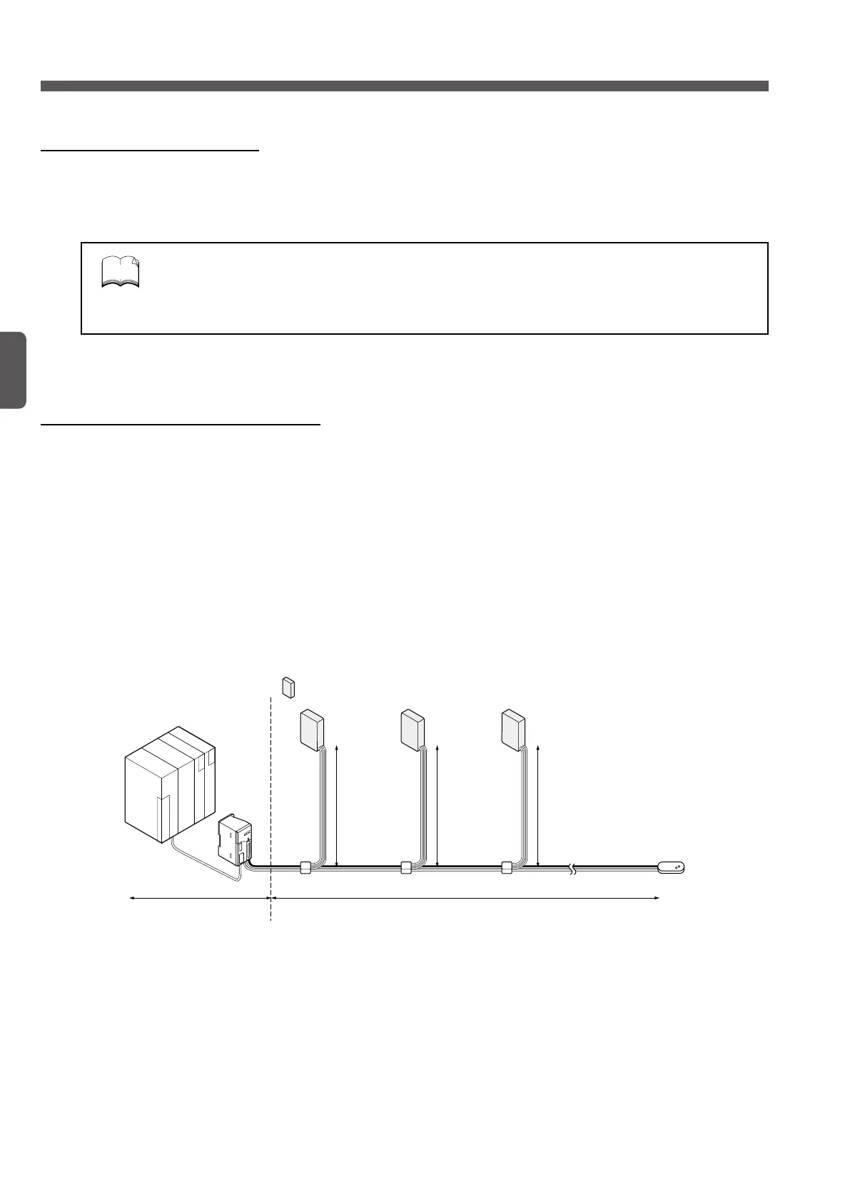
The cable length depends on the total cable length and the transmission distance.
(Main line)
Total cable length =
Control area
: S-LINK V I/O unit
A
A + B + C + D
(Branch line)
B
(Branch line)
C
(Branch line)
D
 Loading...


