EasyManua.ls Logo

Panasonic TH-50PH9UK User Manual

Panasonic TH-50PH9UK
159 pages
To Next Page IconTo Next Page
Page #1 background imageLoading...
Page #1 background image
© 2006 Matsushita Electric Industrial Co., Ltd. All
rights reserved. Unauthorized copying and
distribution is a violation of law.
TH-50PH9UK
GPH9D Chassis
High Definition Plasma Display
Specifications
Power Source 120 V
A
C, 50/60Hz
Power Consumption
Maximum 460 W
Stand-b
y
condition Save OFF 0.5 W, Save ON 0.3 W
Power off condition 0.1W
Plasma Displa
y
panel Drive method:
A
C type 50-inch,
16:9 aspect ratio
Contrast Ratio Ma
x
10000:1
Screen size 43.5” (1,106 mm) (W) × 24.5” (622 mm) (H) × 50” (1,269 mm) (diagonal)
(No. of pixels) 1,049,088 (1,366 (W) × 768 (H) [4,098 × 768 dots]
Operating condition
Temperature 32 °F - 104 °F (0 °C - 40 °C)
Humidit
y
20 % - 80 %
Applicabl
e
signals
Color System NTSC, PAL, PAL60, SECAM, Modified NTSC
Scanning format 525 (480) / 60i 60p, 625 (575)
/
50i 50p, 750 (720)
/
60p 50p, 1125 (1080) / 60i 50i 24p 25p
30p 24sF .... SMPTE274M, 1250 (1080) / 50i
PC signals VGA, SVGA, XGA,
SXGA, UXG
A
..... (compressed)
Horizontal scanning frequency 15 - 110 kHz
Vertical scanning frequency 48 - 120 Hz
Connection terminals
V VIDEO IN / OUT (BNC) 1.0 Vp-p (75-ohm or high impedance)
S VIDEO IN (MINI DIN 4PIN) Y: 1 Vp-p (75-ohm), C: 0.286 Vp-p (75-ohm)
A
UDIO IN (RCA PIN JACK × 2) 0.5 Vrms (high impedance)
COMPONENT / RGB
Y
/ G (BNC) 1.0 Vp-p
/
composite (75-ohm)
0.7 Vp-p
/
non-composite (75-ohm)
P
B
/B (BNC), P
R
/R (BNC) 0.7 Vp-p (75-ohm)
A
UDIO IN (RCA PIN JACK × 2) 0.5 Vrms (high impedance)
PC (HIGH-DENSIT
Y
Mini-D-SUB 15PIN) R,G,B
/
0.7 Vp-p (75-ohm)
ORDER NO. MTNC060689CE
D10 Canada: B07

Table of Contents

Other manuals for Panasonic TH-50PH9UK

Question and Answer IconNeed help?

Do you have a question about the Panasonic TH-50PH9UK and is the answer not in the manual?
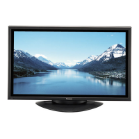
Panasonic TH-50PH9UK Specifications

General IconGeneral
Screen Size50 inches
Resolution1366 x 768 pixels
Panel TypePlasma
Aspect Ratio16:9
Viewing Angle160 degrees
Input TerminalsDVI-D, Component, Composite, S-Video

Summary

Specifications

Applicable Signals

Safety Precautions

General Guidelines

Basic safety guidelines for servicing equipment.

Prevention of Electro Static Discharge (ESD) to Electrostatically Sensitive (ES) Devices

Troubleshooting Guide

Self Check

Automatic check of bus line controlled circuit of plasma display.

Power LED Blinking Timing Chart

Information on LED blinking timing and defective blocks.

No Power

Troubleshooting states of no power indication by power LED.

No Picture

Troubleshooting steps for 'No Picture' condition.

Local Screen Failure

Identifying possible PCB defects for local screen failure.

Block and Schematic Diagram

Schematic Diagram Notes

Notes for understanding schematic diagrams.

P-Board (1 of 2) Schematic Diagram

First part of the P-Board schematic diagram.

PB-Board Block and Schematic Diagram

Block and schematic diagram for the PB-Board.

Main Block Diagram

Overall block diagram of the plasma display system.

P-Board (2 of 2) Schematic Diagram

Second part of the P-Board schematic diagram.

HA-Board Block and Schematic Diagram

Block and schematic diagram for the HA-Board.

P-Board Block Diagram

Block diagram of the P-Board.

HU-Board Block Diagram

Block diagram of the HU-Board.

HU-Board (1 of 2) Schematic Diagram

First part of the HU-Board schematic diagram.

Disassembly

Removal of the Plasma Panel

Location of Lead Wiring

Location of Lead Wiring (1)

Detailed location of lead wiring in the first section.

Location of Lead Wiring (2)

Detailed location of wiring in the second section.

Location of Lead Wiring (3)

Detailed location of wiring in the third section.

Location of Lead Wiring (4)

Detailed location of wiring in the fourth section.

Adjustment Procedure

Driver Set-up

Preparation and setup for driver adjustment.

Initialization Pulse Adjust

Adjusting VR6602 for initialization pulse timing.

P.C.B. (Printed Circuit Board) Remove

Cautionary notes before removing PCBs.

Quick Adjustment After P.C.B. Remove

Quick adjustment details after PCB removal.

Adjustment Volume Location

Location of adjustment volumes on the boards.

Test Point Location

Location of test points for adjustment.

Service Mode

CAT (Computer Aided Test) Mode

Accessing and using the Computer Aided Test mode.

CD Mode

Selecting and operating the CD mode for software version and memory data changes.

MS Mode

Selecting and operating the MS mode for market selection.

IIC Mode Structure

Structure and sample data for IIC mode adjustments.

IIC Mode

Selecting and operating the IIC mode for adjustments.

SD Mode

Selecting and operating the SD mode for input command checks.

ID Mode

Selecting and operating the ID mode for identifying product information.

Adjustment

RGB White Balance Adjustment

Procedure for adjusting RGB white balance using patterns and analyzer.

HD White Balance Adjustment

Procedure for adjusting HD white balance using component output patterns.

Power Control Adjustment

Procedure for adjusting power control and verifying power consumption.

Electrical Replacement Parts List

Related product manuals