85 7641 32
POWER ALARM
MULTISCREEN
QUAD SHIFT
CURSOR
VIDEO SELECT
SELECT
ALARM RESET
ON
OFF
ESC
MENU MODE
SEQ
SET
RESET
PLAY
EL-ZOOM
STILL
MODE SELECT
Quad System WJ-MS
SWITCH
PROTECTER
SENSOR
DSU
DSU
STEP2 STEP3
DIAL
MEMORY
CALL
REDIAL
DELETE
ESC
AUDIO MUTE
MENU
ALM MEMORY
ENTER
TELE WIDE
AF
NEAR
FAR
STEP1
Remote Controller WV-CU20
123
456
78
0
9
12345
#
VIDEO
AUTO/MANU
ALM ACK
ONE TOUCH DIAL
STEP2 STEP3
DIAL
MEMORY
CALL
REDIAL
DELETE
ESC
AUDIO MUTE
MENU
ALM MEMORY
ENTER
TELE WIDE
AF
NEAR
FAR
STEP1
Remote Controller WV-CU20
123
456
78
0
9
12345
#
VIDEO
AUTO/MANU
ALM ACK
ONE TOUCH DIAL
LINE
1
LINE
2
RING.VOL
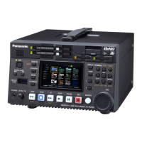
AV Codec WJ–AV
POWER
REMOTE
LINE
1
LINE
2
RING.VOL
AV Codec WJ–AV
POWER
REMOTE
ON
OFF
POWER
ON
OFF
POWER
Controller
Monitor
Controller Monitor
VIDEO IN 1
SENSOR IN/
TRIGGER OUT
Color/black and white camera
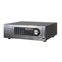
Video quad unit or
sequential switcher
Video output
Spot output
Remote control connector
Coaxial cable
(with BNC plug,
procured on the site)
Special-order cable
(procured on the site)
AV Codec
(transmitter mode)
Remote AV Codec
AV Codec
(receiver mode)
ISDN
(for maintenance)
Monitor
● Connections
If a video quad unit, sequential switcher, etc., are con-
nected, a surveillance system can be established, by
which a maximum of 8 cameras can be switched over.
The video quad unit or the sequential switcher can be
connected by the use of a sensor input/trigger output
connector. A cable provided with a D-Sub 25-pin con-
nector should be prepared separately.
The diagram at the right shows an example of connec-
tions for the video quad unit (WJ-MS488). This diagram
shows the units to be connected and the rear terminal
arrays for this unit. It is not intended to show the con-
nectors on the cable side. For more details, please
refer to the Operating Instructions for the units to be
connected.
[Units to be connected and the rear side view of this unit]
■
Example of Connections with Video Quad Unit or Sequential Switcher
Remote site Control site
 Loading...