16
6K Hardware Installation Guide
PIN OUTS & SPECIFICATIONS — STEPPER DRIVES ONLY
(15-pin “DRIVE” connectors)
Pin
* Name In/Out Description
1 Step + OUT Differential output. Step (pulse) output to the drive. Step + signal is active high.
Signal levels: Low
≤
1.0VDC @ -30mA, High
≥
3.5VDC @ +30mA.
2 Direction + OUT Differential output. High signal on Direction + specifies motion in the positive direction; Low signal on
direction + specifies motion in the negative direction.
Signal levels: Low
≤
1.0VDC @ -30mA, High
≥
3.5VDC @ +30mA.
4 Stall IN Encoder-less Stall Detection input for use with the GEMINI drive.
5 DFT IN Drive fault input. Set active level with the
DRFLVL
command (default is active low). The drive fault input
will not be recognized until you send a
DRFEN1
command (enables the input) to the axis. Voltage range
for the DFT input is 0-24V. Switching levels: Low
≤
1/3 VINref voltage, High
≥
2/3 VINref voltage (factory
default VINref voltage is +24VDC, but you can connect a different voltage to the VINref terminal**). To
make DFT a sinking input, connect the CNTRL-P terminal** to the GND terminal**.
9
Step
–
OUT
Differential output. Step (pulse) output to the drive. Step
–
signal is active low.
10
Direction
–
OUT
Differential output. Low signal on Direction
–
specifies motion in the positive direction; High signal on
direction
–
specifies motion in the negative direction.
11 Shutdown + OUT Differential output. This signal is used to turn off current in the motor windings.
High signal on Shutdown + indicates the motor winding current should be off.
Signal levels: Low
≤
1.0VDC @ -30mA, High
≥
3.5VDC @ +30mA.
12
Shutdown
–
OUT Differential output. This signal is used to turn off current in the motor windings.
Low signal on Shutdown
–
indicates the motor winding current should be off.
13 ISO GND ----- Isolated logic ground.
* Pin 3-4, 6-8, and 15 are reserved for connection to a
±
10V analog servo drive (see page 10).
** The VINref, CNTRL-P, and GND terminals are located on the screw-terminal connector on top of the 6K chassis.
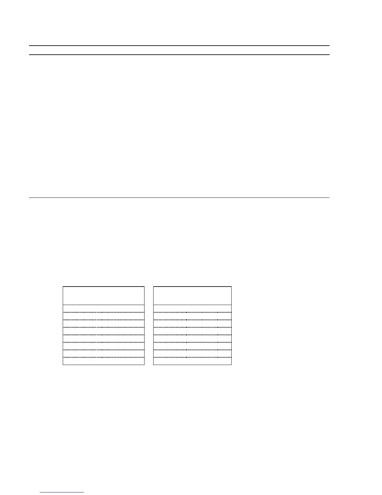
CONNECTIONS TO THE ZETA, S, OEM750 and PDS DRIVES
Drive Connections 6K Connections
Signal Name Connector Pin Signal Name Connector Pin
Step + 25-pin 01
↔
Step + DRIVE 01
Step – 25-pin 14
↔
Step – DRIVE 09
Direction + 25-pin 02
↔
Direction + DRIVE 02
Direction – 25-pin 15
↔
Direction – DRIVE 10
Shutdown + 25-pin 16
↔
Shutdown + DRIVE 11
Shutdown – 25-pin 17
↔
Shutdown – DRIVE 12
Fault Output 25-pin 09
↔
Drive Fault DRIVE 05
Fault Return 25-pin 21
↔
Ground DRIVE 13
NOTES
:
•
The PDS drive requires a
PULSE
command setting of 1.0 (
PULSE1.0
).
•
Use the 10-foot cable (p/n 71-016137-10) for plug compatibility.
 Loading...