Chapter 1. Installation
19
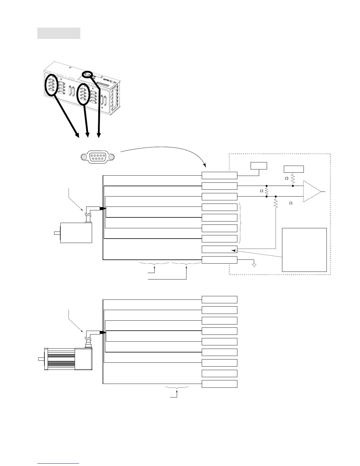
Encoders
(“ENCODERS” and “MASTER ENCODER” connectors)
Incremental
Encoder
+5VDC
Red
A Channel -
Brown/White
A Channel +
Brown
B Channel +
Green
B Channel -
Green/White
Z Channel +
Orange
Z Channel -
Orange/White
Ground
Black
SM, N, or J Series Motor
ENCODER Connector
15
69
Internal Schematic
1.3 K
6.81 K
243
ISO GND
+5VDC
+5VDC
Pin 2 (A+)
Pin 3 (A-)
Pin 4 (B+)
Pin 5 (B-)
Pin 6 (Z+)
Pin 7 (Z-)
Pin 8 (SE)
Pin 1 (+5V out)
Pin 9 (GND )
To use single-ended
encoders, jumper this
pin to GND (pin 9).
Then leave A-, B- and
Z- not connected.
This is not available
on the "MASTER
Encoder" connector.
Same circuit as
the A Channel
Wire colors for -RE, -RC, -EC and -E encoders
Red
(n/a)
White
Brown
(n/a)
Blue
(n/a)
Black
Wire colors for -HJ encoders
+5VDC
Red
A Channel +
White
A Channel -
Yellow
B Channel +
Green
B Channel -
Blue
Z Channel +
Orange
Z Channel -
Brown
Ground
Black
Pin 2 (A+)
Pin 3 (A-)
Pin 4 (B+)
Pin 5 (B-)
Pin 6 (Z+)
Pin 7 (Z-)
Pin 8 (SE)
Pin 1 (+5V out)
Pin 9 (GND )
Wire colors for SM, N and J encoder cables
Max. cable length is
100 feet (30.48 m)
Use 22 AWG wire.
Encoder cable
ENCODER INPUTS:
Differential comparator accepts two-phase quadrature incremental encoders
with differential (recommended) or single-ended outputs. Max. frequency is
12.0 MHz post quadrature. TTL-compatible voltage levels: Low
≤
0.4V,
High
≥
2.4V. Maximum input voltage is 5VDC.
MASTER ENCODER:
The master encoder is used for Following, and not for servo feedback or
stepper stall detect. The pin outs are the same as the other encoders, except
that pin 8 is ISO GND (can’t use a single-ended encoder).