Chapter 1. Installation
15
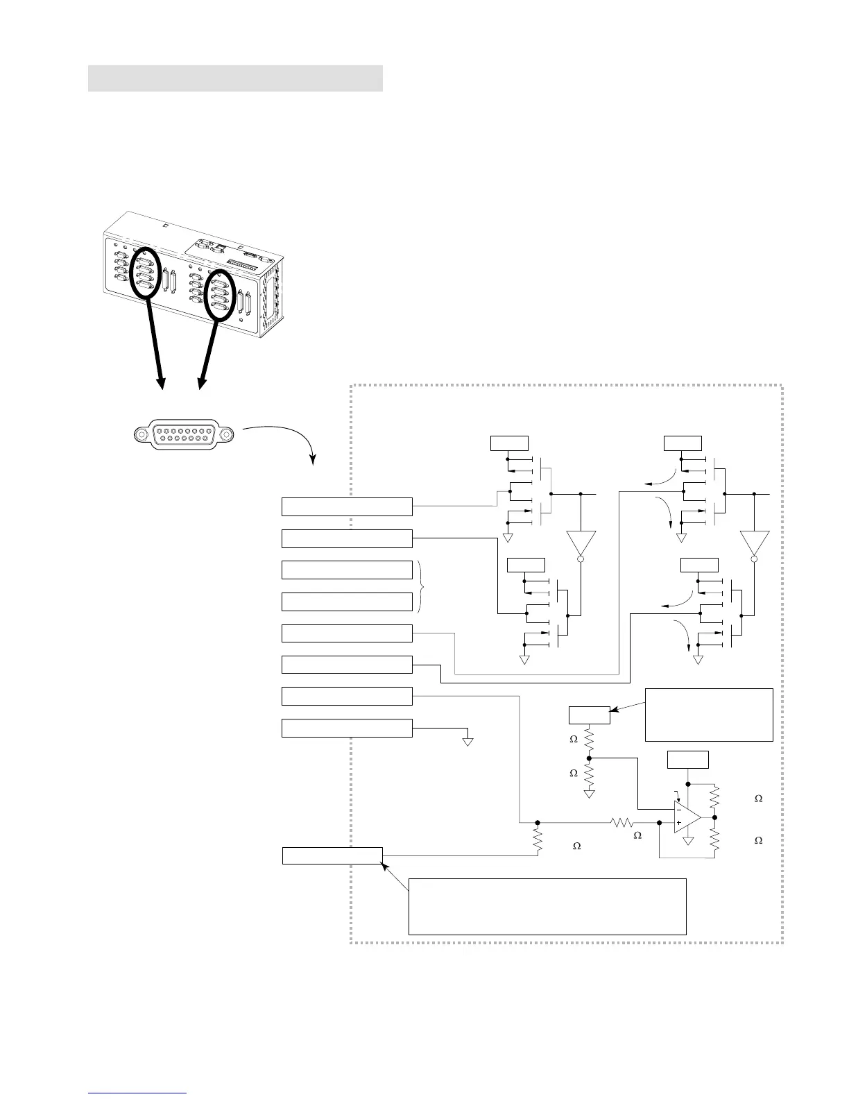
Drives: Step & Direction Drives
(“DRIVES” connectors)
INTERNAL SCHEMATICS
ISO GND
VINref
20.0 K
18.2 K
DRIVE Connector
Pin 02 (DIRECTION +)
Pin 10 (DIRECTION -)
Pin 13 (ISO GND)
18
915
Internal Schematic
LM339
24VDC
CNTRL-P Terminal
Same circuit
design as
Step
12.0 K
6.8 K
33.0 K
33.0 K
Isolated Ground
Current Flow: Active vs. Inactive
ISO GND
Pin 05 (DRF)
By default, the Drive Fault input is a sourcing input.
If you wish the Drive Fault input to sink current, connect
"CNTRL-P" to "GND" on the screw-terminal connector
located on top of the 6K chassis.
+5VDC
+5VDC
ISO GND
Active
Inactive
Active
Inactive
ISO GNDISO GND
+5VDC
+5VDC
Pin 01 (STEP +)
Pin 09 (STEP -)
Pin 06 (CMD - )Pin 12 (SHUTDOWN - )
Pin 11 (SHUTDOWN +)
VINref is +24VDC, unless
you connect an external
5-24VDC supply to the
VINref terminal.
Drive Cable
:
Maximum recommended length is 50 feet (15.24 m).
Use 22 AWG wire.
 Loading...