14
6K Hardware Installation Guide
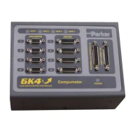
CONNECTIONS TO THE SV DRIVE
SV Drive Connections 6K Connections
Signal Name Connector Pin Signal Name Connector Pin
SOLL + X8 01
↔
CMD + DRIVE 03
SOLL – X8 02
↔
CMD – DRIVE 06
N X13 02
↔
Z + ENCODER 06
B X13 03
↔
B + ENCODER 04
A X13 04
↔
A + ENCODER 02
GND X13 05
↔
ISO GND DRIVE 13
N/ X13 09
↔
Z – ENCODER 07
B/ X13 10
↔
B – ENCODER 05
A/ X13 11
↔
A – ENCODER 03
+5V In X13 13
↔
+5V Out ENCODER 01
ENABLE X10 01
↔
COM DRIVE 14
FAULT OUTPUT X10 15
↔
DRIVE FLT DRIVE 05
+24V OUT X10 09
↔
SHTNO * DRIVE 07
ENABLE GND
+24V OUT GND
X10
X10
08
10
Short these terminals together
+24V IN
GND for +24V
X10
X10
14
16
External 24VDC
Power Supply
–+
* The SHTNO relay output is active (disabling the drive) when no power is
applied to the 6K. When the 6K is powered up, the shutdown relay
remains active until you issue a
DRIVE1
command to the axis.
NOTE: Adding the 500
Ω
resistor assumes the drive fault input is pulled up.
(CNTRL-P is internally pulled up to the voltage at the VINref terminal — if no
voltage is connected to VINref, CNTRL-P is pulled up internally to 24VDC.)
However, if all axes are SV drives, do not connect the 500
Ω
resistor; instead,
connect the CNTRL-P pin to GND.
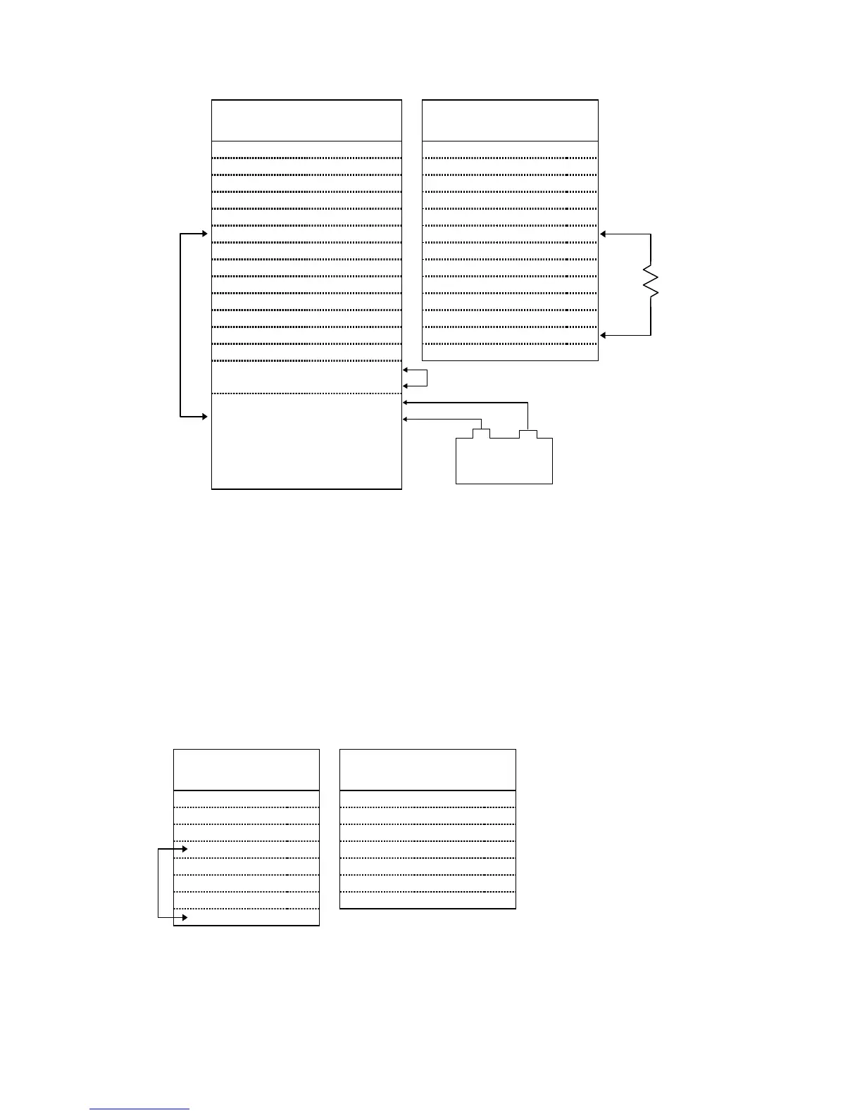
CONNECTIONS TO THE TQ10 DRIVE
TQ Drive Connections 6K Connections
Signal Name Pin Signal Name Connector Pin
ENABLE IN 01
↔
SHTNO DRIVE 07
ENABLE GND 02
↔
COM DRIVE 14
FAULT OUT + 03
↔
DFT DRIVE 05
FAULT OUT – 04
↔
AGND DRIVE 15
COMMAND + 07
↔
CMD + DRIVE 03
COMMAND – 08
↔
CMD – DRIVE 06
COMMAND SHLD 09
↔
(Cable Shield) --------- ----
GND 10
See note below.
Connect the SV’s
GND (X13 pin 05)
to the ground from
the external 24VDC
power supply.
Jumper pins
04 and 10.
500
Ω
 Loading...