Chapter 1. Installation
21
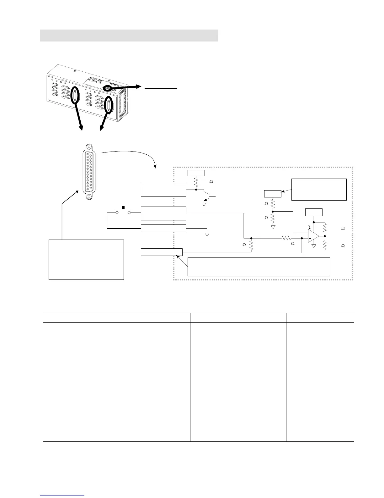
Onboard Programmable Inputs and Outputs
TRIGGERS/OUTPUTS
Connector
VINref
24VDC
20.0 K
18.2 K
Internal Schematic
LM339
24VDC
TRIG-P Terminal
VINref is +24VDC, unless
you connect an external
5-24VDC supply to the
VINref terminal.
12.0 K
6.8 K
33 K
33.0 K
33.0 K
By default, the trigger inputs are sourcing inputs. If you wish all of the
trigger inputs to sink current, connect "TRIG-P" to "GND" on the
screw-terminal connector located on top of the 6K chassis.
GND (even # pin)
Trigger Input
(odd # pins 9-23)
ISO GND
ISO GND
Open Collector
ISO GND
1
14
25
13
Output
(odd # pins 1-7)
PIN OUTS & SPECIFICATIONS
(25-pin “TRIGGERS/OUTPUTS” connectors)
Pin
#
* In/Out Description
(axes 1-4)
Description
(axes 5-8)
Spes for Trigger Inputs Specs for GP Outputs
25
23
21
19
17
15
13
11
9
7
5
3
1
-----
IN
IN
IN
IN
IN
IN
IN
IN
OUT
OUT
OUT
OUT
RESERVED
Trigger input 1
(TRIG-1A)
Trigger input 2
(TRIG-1B)
Trigger input 3
(TRIG-2A)
Trigger input 4
(TRIG-2B)
Trigger input 5
(TRIG-3A)
Trigger input 6
(TRIG-3B)
Trigger input 7
(TRIG-4A)
Trigger input 8
(TRIG-4B)
GP Output 1
GP Output 2
GP Output 3
GP Output 4
(GP = general purpose)
RESERVED
Trigger input 9
(TRIG-5A)
Trigger input 10
(TRIG-5B)
Trigger input 11
(TRIG-6A)
Trigger input 12
(TRIG-6B)
Trigger input 13
(TRIG-7A)
Trigger input 14
(TRIG-7B)
Trigger input 15
(TRIG-8A)
Trigger input 16
(TRIG-8B)
GP Output 5
GP Output 6
GP Output 7
GP Output 8
•
Voltage range is 0-24VDC.
•
Trigger input s
witching levels:
Low
≤
1/3 VINref voltage, High
≥
2/3
VINref voltage (factory default VINref
voltage is +24VDC, but you can
connect a different voltage to the
VINref terminal**). To make all limit
inputs sinking inputs, connect the
TRIG-P terminal** to the GND
terminal**.
•
Status: Check with
TIN
or
IN
.
•
Programmable functions with the
INFNC
command. Can also be used as
a “Trigger Interrupt” input (
INFNCi-H
)
for position capture and registration.
•
Active level is set with the
INLVL
command. Default is active low (see
n.o. switch in diagram above).
•
Open collector output;
will sink up to 300mA.
•
Status: Check with
TOUT
or
OUT
.
•
Programmable
functions with the
OUTFNC
command. Can
also be used as an
“Output on Position”
output (
OUTFNCi-H
).
•
Active level is set with
the
OUTLVL
command.
Default is active low.
•
If the outputs are
driving inductive loads,
connect the OUT
DIODE terminal to
24VDC.
* All even number pins are connected to isolated logic ground.
** The VINref, TRIG-P, and GND terminals are located on the screw-terminal connector on top of the 6K chassis.
Master Trigger: The “MASTER TRIG” input on this
connector has the same circuit design as trigger
inputs on the “TRIGGERS/OUTPUTS” connectors.
For easy screw-terminal
connections, use the “VM25”
screw-terminal converter (sold
separately, includes 2-foot
cable). Connection instructions
are provided on page 41.
 Loading...