22
6K Hardware Installation Guide
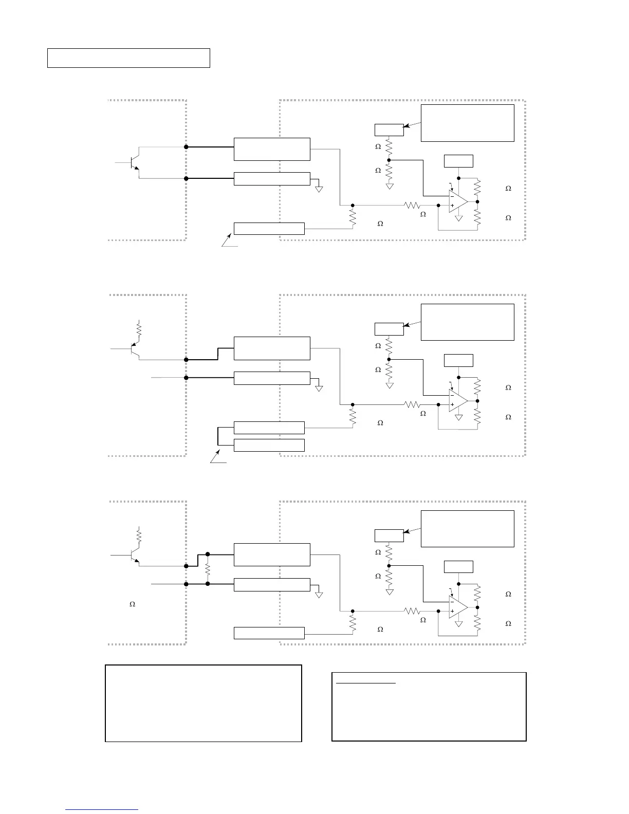
Trigger Input Connections
VINref
20.0 K
18.2 K
Electronic Device 6K Internal Schematic
LM339
24VDC
TRIG-P Terminal
VINref is +24VDC, unless
you connect an external
5-24VDC supply to the
VINref terminal.
12.0 K
6.8 K
33.0 K
33.0 K
GND (even # pin)
Trigger Input
(odd # pins 9-23)
ISO GND
ISO GND
Output
Ground
The output should
be able to sink at
least 1mA of current.
VINref
20.0 K
18.2 K
Electronic Device 6K Internal Schematic
LM339
24VDC
TRIG-P Terminal
GND Terminal
VINref is +24VDC, unless
you connect an external
5-24VDC supply to the
VINref terminal.
12.0 K
6.8 K
33.0 K
33.0 K
GND (even # pin)
Trigger Input
(odd # pins 9-23)
ISO GND
ISO GND
Output
Ground
The trigger input is sinking current (TRIG-P connected to GND).
Connection to a Sinking Output Device
Connection to a Sourcing Output Device
V
1
R
1
The trigger input is sourcing to VINref (factory default: VINref is at 24VDC).
Therefore, no connection is required if sourcing 24VDC is appropriate for your needs.
To source to a different voltage, connect a different external supply to VINref.
VINref
20.0 K
18.2 K
Electronic Device 6K Internal Schematic
LM339
24VDC
TRIG-P Terminal
VINref is +24VDC, unless
you connect an external
5-24VDC supply to the
VINref terminal.
12.0 K
6.8 K
33.0 K
33.0 K
GND (even # pin)
Trigger Input
(odd # pins 9-23)
ISO GND
ISO GND
Output
Ground
Typical value for R
is 450
(assuming
R
1
= 0). The value of
R may vary depending
on the value of R
1
and V
1
.
Connection to a Combination of Sinking and Sourcing Outputs
V
1
R
R
1
If you are connecting to a combination of sinking and
sourcing output, connect the VINref terminal to the
voltage supply (factory default is internally connected
to 24VDC) to accommodate the sinking outputs. Then
for each input connected to a sourcing output, wire an
external resistor between the trigger input and GND.
The resistor provides a path for current to flow from
the device when the output is active.
Programming Tip: If connecting to sinking output, set
the trigger’s
INLVL
setting to active low (
INLVL0
). If
connecting to a sourcing output, set the trigger’s
INLVL
setting to active high (
INLVL1
). Thus, when
the output is active, the
TIN
/
IN
status will report a “
1
”
(indicates that the input is active), regardless of the
type of output that is connected.
 Loading...