Chapter 1. Installation
13
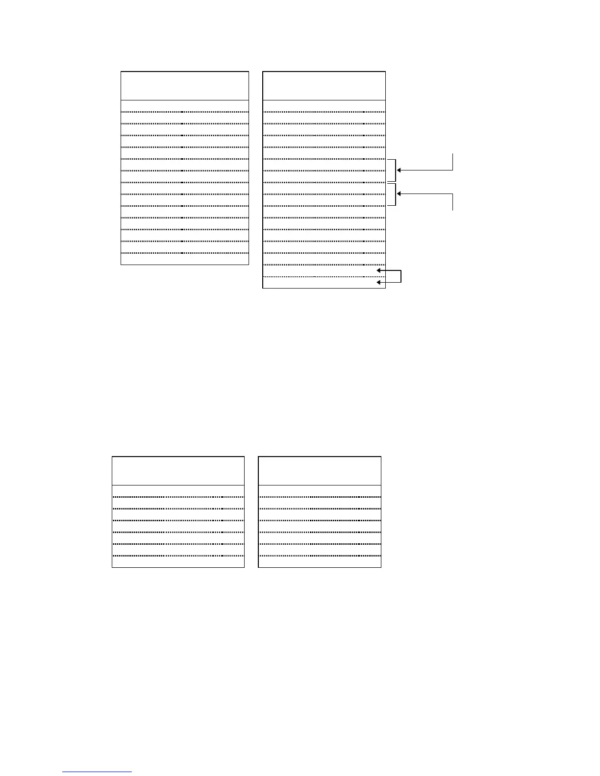
CONNECTIONS TO THE LINEARSERV DRIVE
Linearserv Connections 6K Connections
Signal Name Connector Pin Signal Name Connector Pin
Com + CN1 01
↔
+5V ENCODER 01
Servo On – CN1 05
↔
SHTNO DRIVE 07
A + CN1 17
↔
A + ENCODER 02
B + CN1 19
↔
B + ENCODER 04
Z + CN1 21
↔
Z + ENCODER 06
Agnd-TQ CN1 22
↔
CMD – DRIVE 06
Vin-TQ CN1 23
↔
CMD + DRIVE 03
Agnd-VEL CN1 24
↔
CMD – DRIVE 06
Vin-VEL CN1 25
↔
CMD + DRIVE 03
Com – CN1 26
↔
AGND DRIVE 15
Ready + CN1 31
↔
DFT DRIVE 05
A – CN1 41
↔
A – ENCODER 03
B – CN1 43
↔
B – ENCODER 05
Z – CN1 45
↔
Z – ENCODER 07
COM DRIVE 14
GND ENCODER 09
NOTE
: The Linearserv’s default setting is for Position Mode (for accepting step
and direction command signals). The connections above assume the
Linearserv is reconfigured for Velocity Mode or Torque Mode. Refer to
the Linearserv user guide for additional information.
CONNECTIONS TO THE OEM670T & OEM675T DRIVE
OEM67x Drive Connections 6K Connections
Signal Name Pin Signal Name Connector Pin
CMD + 01
↔
CMD + DRIVE 03
CMD – 02
↔
CMD – DRIVE 06
FAULT 09
↔
DFT DRIVE 05
ENABLE 10
↔
SHTNO DRIVE 07
GND 11
↔
COM DRIVE 14
GND 16
↔
AGND DRIVE 15
GND 07
↔
GND DRIVE 13
When the Linearserv is in Torque
Mode, connect Agnd-TQ to CMD –,
and connect Vin-TQ to CMD +.
When the Linearserv is in Velocity
Mode, connect Agnd-VEL to CMD –,
and connect Vin-VEL to CMD +.
Jumper COM to
round (GND).
 Loading...