The loop impedance is the sum of all the resistance components of
a current loop, which is traversed in an error from the error stream.
The resistance should be as low as possible, so that at high fault
currents no heat is generated in the lines and thereby no fire may
result.
The prospective fault current indicates the error in the case flowing
through the grounding current, which is determined from the loop
impedance. The PFC should be used to dimension the protective
devices used in accordance with that tripping the over current
protection devices can take place.
The prospective short-circuit current (PSC) is the current flowing in
the event of a fault current between phase and neutral. This is
determined by the LN loop impedance and must be large enough
so that the installed over-current protection devices can trigger.
The loop impedance measurement generates a test current against
the ground. Should a leakage circuit breaker be part of the test
system, it can be triggered. When the RCD is triggered, testing
cannot be completed, therefore the tests should be used as "No
Trip" (not trigger), so the RCD won’t trigger.
In a loop impedance measurement in test circuits without a RCD
"Hi Amp" function should be used, which uses a full test (high
amps) to the ground.
The zero function (zeroing) measures the inherent resistance of the
test leads and subtracted to obtain this value from the loop
impedance for precise measurement results.
Shows the measured voltage (V) and the frequency (Hz) between
the selected lines (LN, L-N-PE or PE).
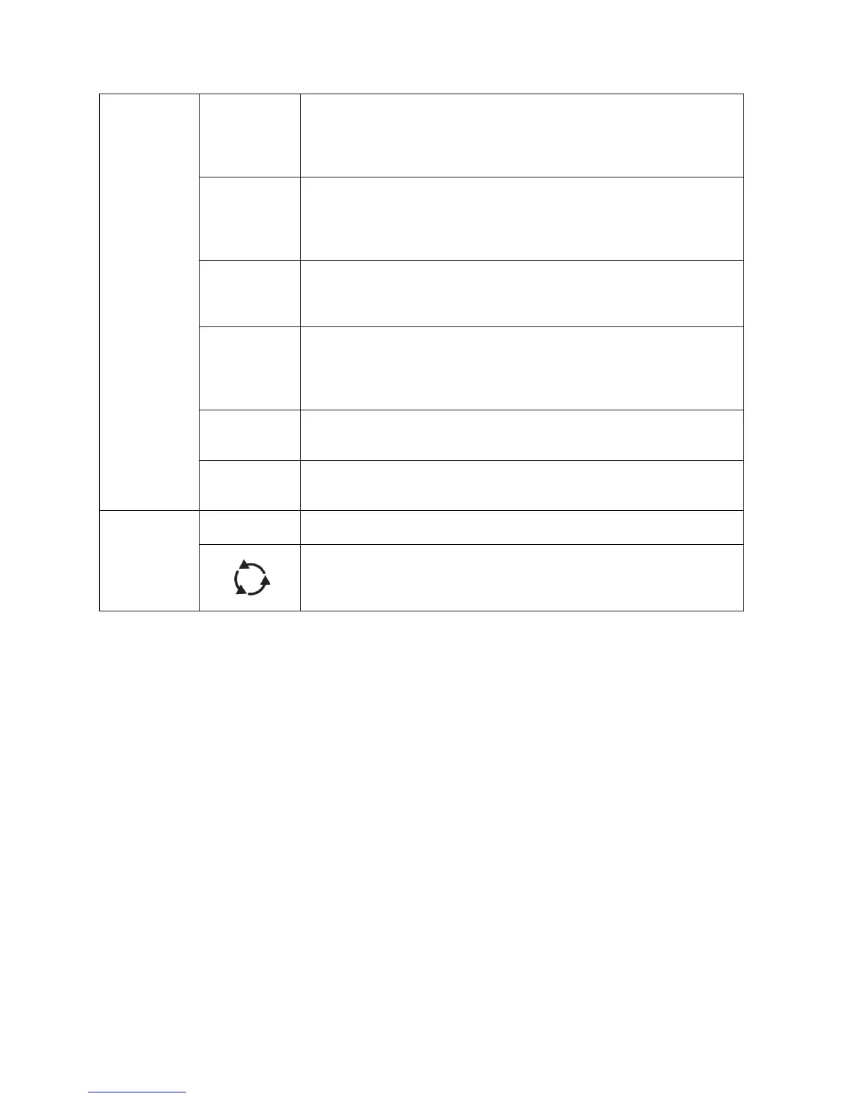
The phase sequence indicator is used to check the correct
connection of three-phase systems. With the correct phase
sequence (L1, L2, L3) it shows "123" in the display and reversed
phase is shown as "213".