5
Outline of Assembly and Disassembly
1. Caution
(1)Be sure to use the anti-static mat and wrist strap to prevent static failure of circuits.
(2) This product is used lead free solder.
Surface of solder will be white-tinged color. Solder quickly, because melting temperature is
high and so if heat to much, it is possible to damage to PC board.
Soldering iron requirement: The temperature can be adjusted up to 400º and exclusive use
for lead free solder. Also it is desirable to use antistatic soldering iron.
The temperature for tip of soldering iron must set between 340º ~ 360º for lead free solder.
(3) Do not stress to the connector terminals and flexible boards because they are very delicate
parts. Pay careful attention to the connector terminals and flexible boards and, we
recommend marking to the flexible board before disconnecting them. This will be helpful
to reconnect the flexible board to the connector terminal properly.
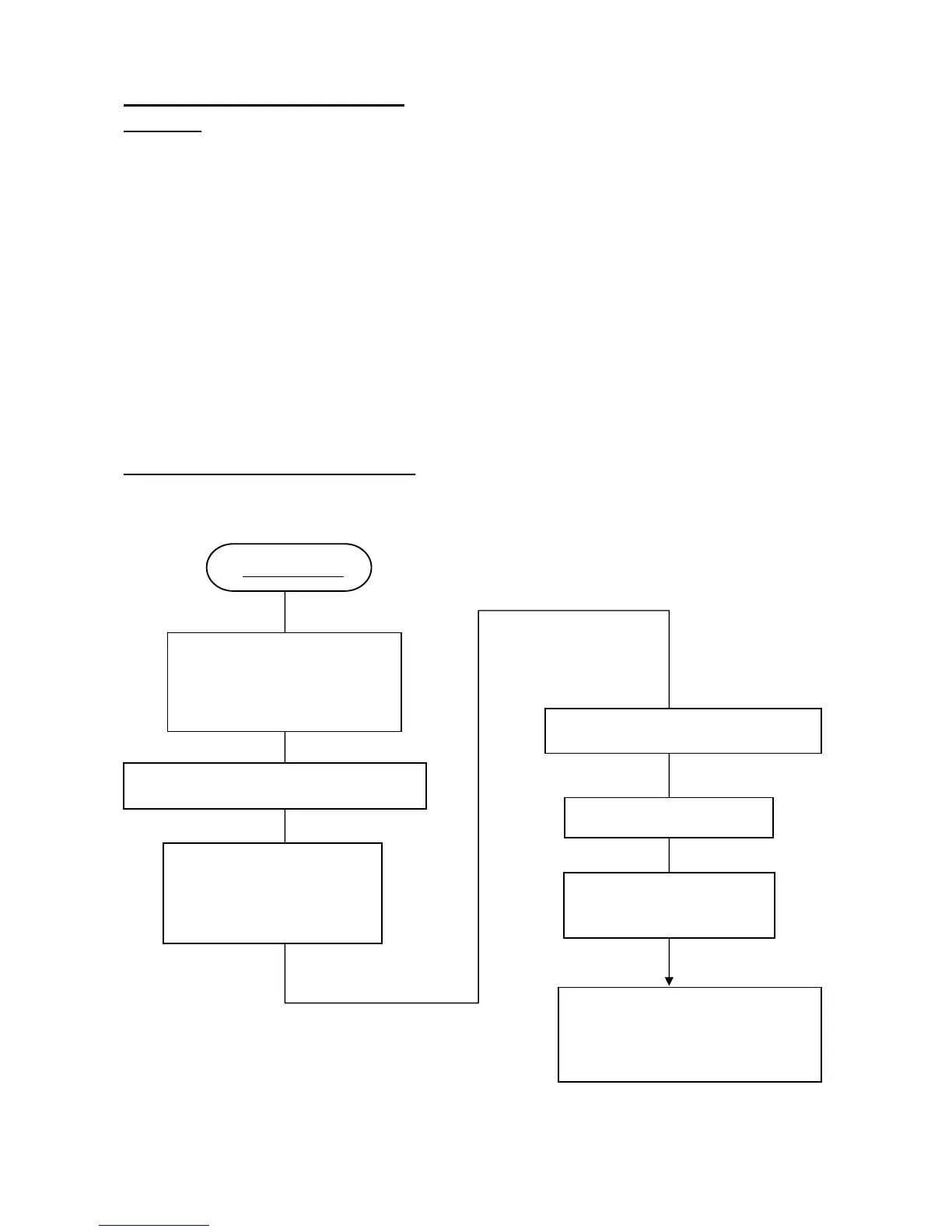
2. Adjustment Flow when replace T100
Following flow chart is method for adjustment when replacing T100.
Replace T100
[Function check]
*SR operation can be skipped
When SR adjustment is completed
[Adjustment]
*Install FW for replacing T100
*Install initial data
SR adjustment I (SR unit adjustment)
SLR function adjustment
(Program software)
Can not be initialized data
SR adjustment II (SR gain adjustment)
Digital Adjustment
Shutter speed adjustment
(Histogram)
 Loading...