26
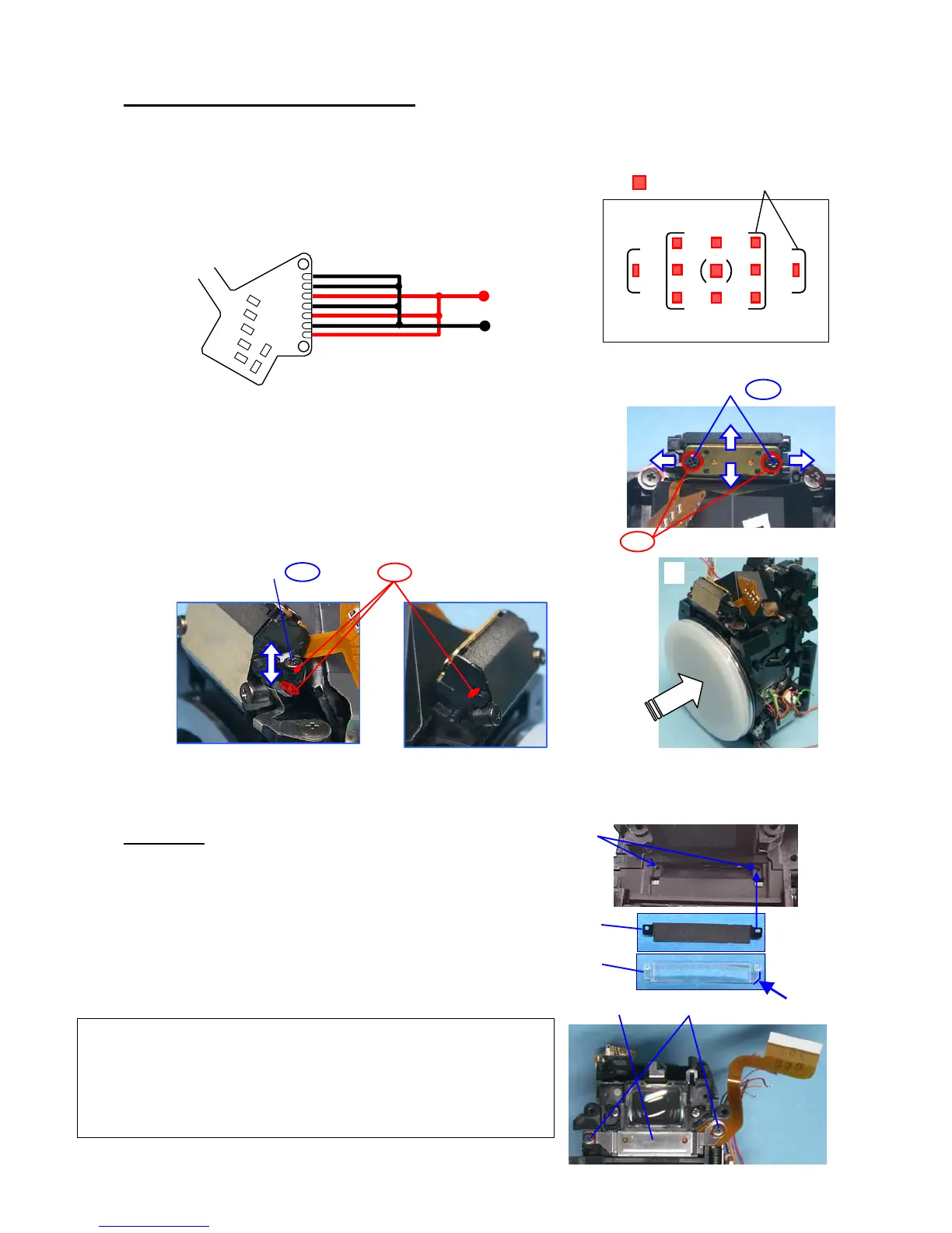
13. [ADJUST] POSITIONING SI-LED
[Required equipment]Power supply, lead wires
① Solder and arrange the lead wires on 0-O170 as shown in the figure below.
[Caution]Do not stress to the lands of 0-O170.
② Apply DC3.2V to 0-O170, and confirm the positioning
And lighting of SI-LED 11points.
③ [ADJ-1]Loosen 2 screws, and then adjust the position of 0-O170.
④ Tighten 2 screws, and then confirm the position again.
⑤ [ADJ-2]Turn adjusting screw to adjust fine adjustment for up
and down position then confirm the position again.
⑥ After adjustment is done, apply the screw-lock to 5 points
and remove the lead wires from 0-O170.
⑦ A mount cover is attached in order to protect a SI-LED part hitting during work.
14. 0-O100
① Apply small amount of dia bond (Black) as shown in figure.
② M9
③ M2 prism -- Make sure that there is no dust on M2.
④ 0-O100
⑤ TY-CNL-F1.7x3.0 x2 -- Temporally tighten screws while
holding 0-O100 plate.
: SI-LED AF frame
(+) DC3.2V
(-)
0-O170
①
②
①
②
③
④
⑤
[Note of Disassembly]
1. Remove the screw lock which is stick to the screw.
2. Unscrew (x2) while pressing the plate of 0-O100.
3. If M2 does not replace, you do not necessary to disassemble.

 Loading...