112 KENR6933
Troubleshooting Section
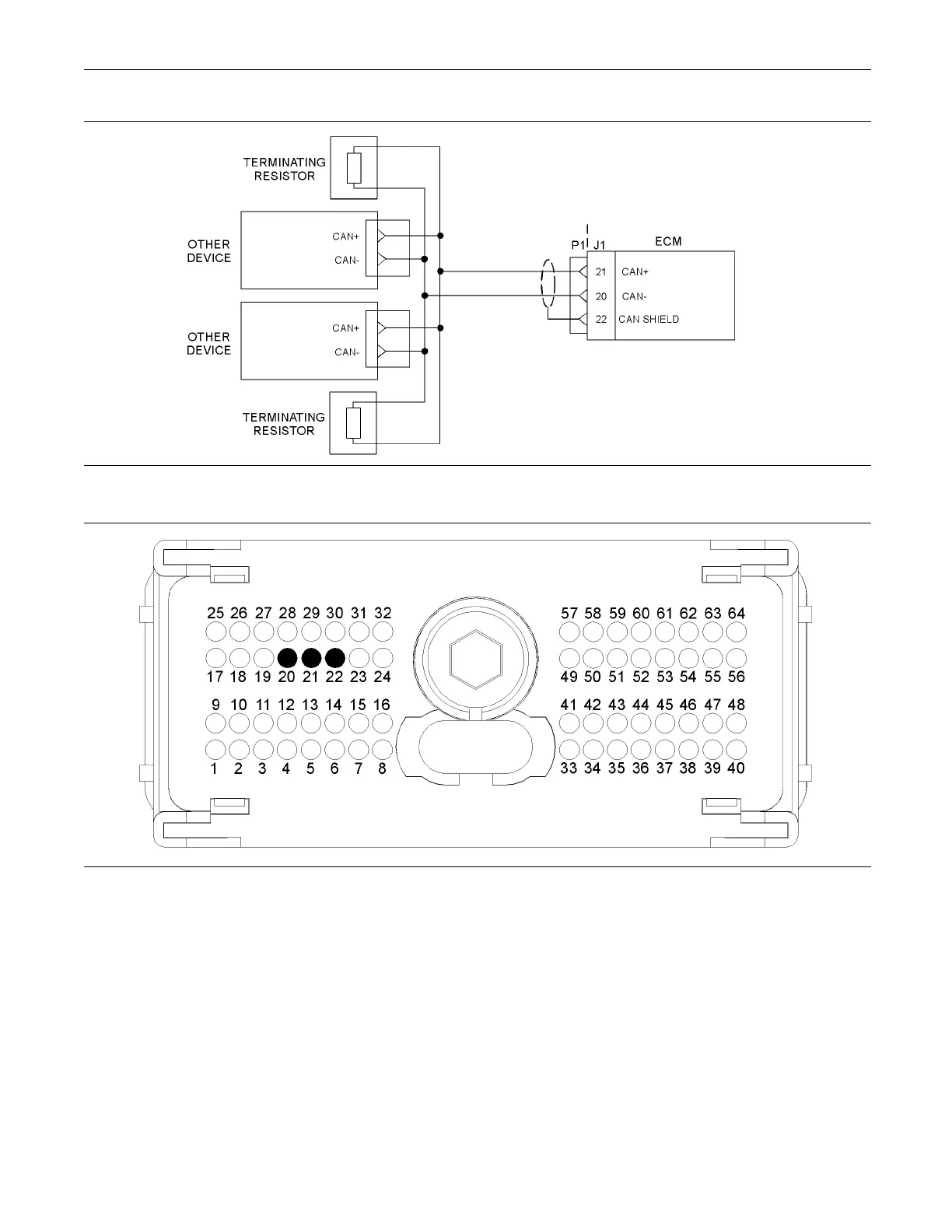
g01244083
Illustration 25
Typical e xample of the schematic for the CAN data link
g01209013
Illustration 26
Typical view of the P1 connector pin locations
(20) CAN- (21) CA N+ (22) CAN Shield
Test Step 1. Insp ect Electrical Connectors
and Wiring.
A. Turn the keyswitch to the OFF position.
B. Thoroughly inspect the harness connector P1/J1
and any other connectors in the CAN data link
circuit.
Refer to Troubleshooting, “Electrical Connectors -
Inspect” for details.
C. Perform a 45 N (10 lb) pull test on each of the
wires that are associated with the CAN data link.
Refer to Illustration 26.
D. Check the harness for abrasion and pinch points
from the keyswitch to the ECM.
Expected Result:
All connectors, pins and sockets should be completely
coupled and/or inserted. The harness should be free
of corrosion, abrasion and/or pinch points.