KENR6933 121
Troubleshooting Section
The flash file in the Electronic Control Module (ECM)
is from the wron
genginefamily.Theenginewillnot
start.
Correct the Co
ndition
Determine the diagnostic code that is active.
Expected Result:
A 0253-02 diag
nostic code is active.
Results:
•
A 0253-02 code is active
Repair: Obtai
n the engine serial number. Use
PTMI to determine the latest available flash file for
the engine. Verify that the latest available flash file
is loaded into
the ECM.
STOP.
i02499732
Electrical Connectors - Inspect
System Opera
tion Description:
Most electrical faults are caused by poor connections.
The followin
g procedure will assist in detecting faults
in connectors and wiring. If a fault is found, correct
the condition and verify that the fault is resolved.
Intermittent electrical faults are sometimes resolved
by disconnecting and reconnecting connectors.
It is very im
portant to check for diagnostic codes
immediately before disconnecting a connector.
Also check for diagnostic codes after reconnecting
the connec
tor. If the status of a diagnostic code is
changed due to disconnecting and reconnecting a
connector, there are several possible reasons. The
likely rea
sons are loose terminals, improperly crimped
terminals, moisture, corrosion, and inadequate
mating of a connection.
Follow these guidelines:
•
Always us
ea27610285 RemovalTooltoremove
the pins from the P1/P2 connectors.
•
Always us
ea2900A033 CrimpTooltoservice
Deutsch HD and DT connectors. Never solder the
terminals onto the wires.
•
Always use a 28170079 RemovalTooltoremove
wedges from DT connectors. Never use a
screwdri
ver to pry a wedge from a connector.
•
Always use a 2900A033 CrimpTooltoservice
AMP seal c
onnectors.
•
Refer to Troubleshooting, “E CM Harne ss
Connector Term
inals” in order to service the
connectors for the Electronic Control Module
(ECM).
•
Always use a breakout harness for a voltmeter
probe or a test light. Never break the insulation of a
wire in order
to access a circuit for measurements.
•
If a wire is cut, always install a new terminal for
the repair.
The connection of any electrical equipment and
the disconnection of any electrical equipment may
cause an explosion hazard which may result in in-
jury or death. Do not connect any electrical equip-
ment or disconnect any electrical equipment in an
explosive atmosphere.
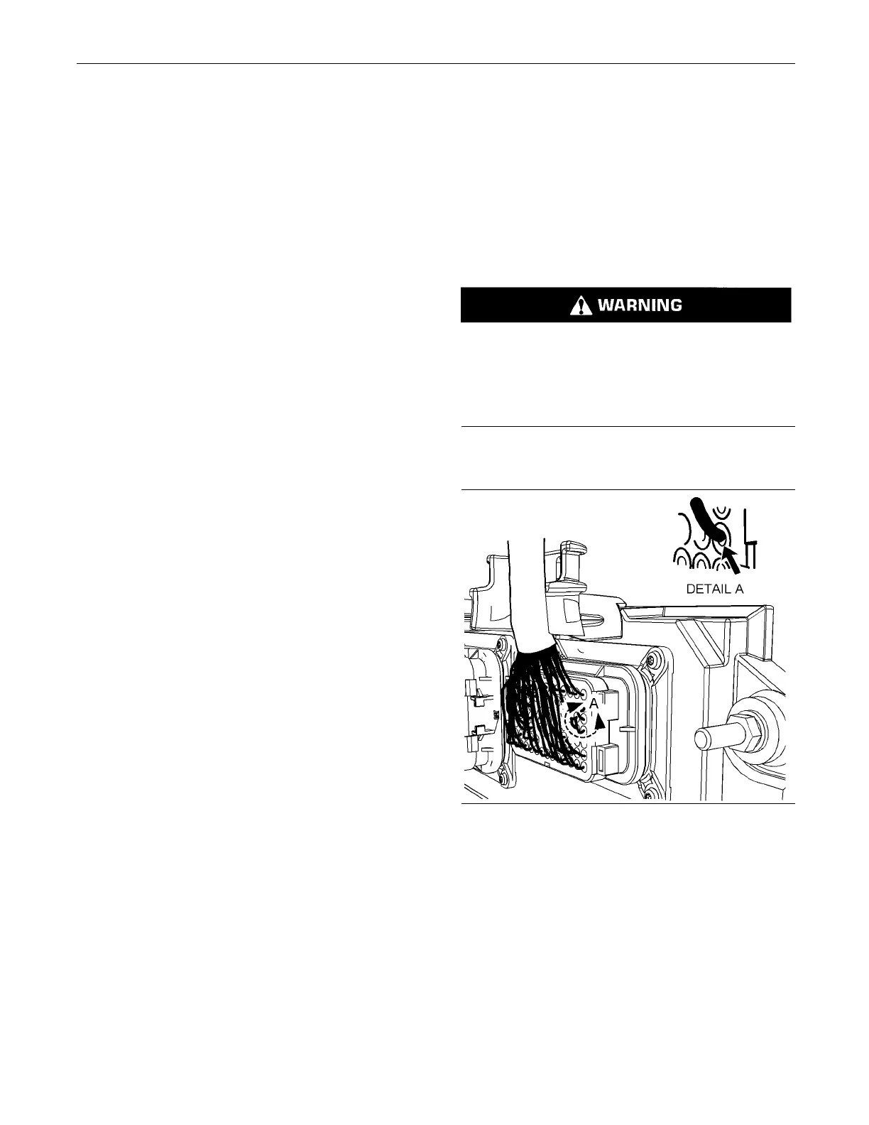
Test Step 1. C heck Connectors for
Moisture and Corrosion
g01131211
Illustration 33
Leaky seal at the connector (typical exam ple)
A. Inspect all the harnesses. Ensure that the routing
of the wiring harness allows the wires to enter the
face of each connector at a perpendicular angle.
Otherwise, the wire will deform the seal bore.
Refer to Illustration 33. This will create a path for
the entrance of moisture. Verify that the seals for
the wires are sealing correctly.