124 KENR6933
Troubleshooting Section
Test Step 4. Perform a Pull Test on Each
Wire Terminal Connection
g01237430
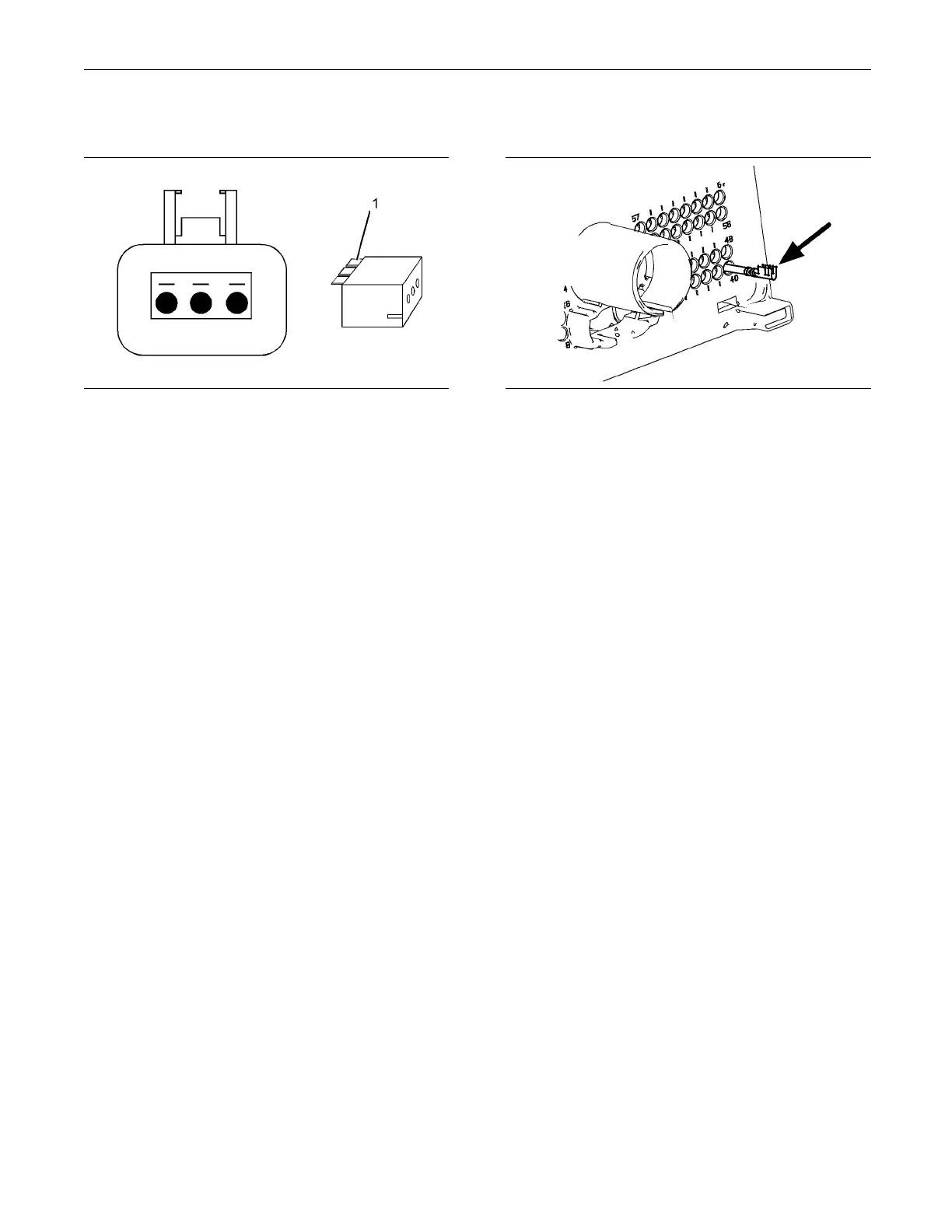
Illustration 37
A typical exam ple of the lock wedge.
(1) Lock wedg
e
A. Ensure that the locking wedge for the connector
is installe
d correctly. Terminals cannot be retained
inside the connector if the locking wedge is not
installed correctly.
B. Perform the 45 N (10 lb) pull test on each wire.
Each terminal and each connector should easily
withstand 4
5 N (10 lb) of tension and each wire
should remain in the connector body. This test
checks whether the wire was correctly crimped
in the term
inal and whether the terminal was
correctly inserted into the connector.
Expected R
esult:
Each terminal and each connector easily withstands
45 N (10 lb)
of pull and each wire remains in the
connector body.
Results:
•
OK – All terminals pass the pull test. Proceed t o
Te s t S t e p
5.
•
Not OK – A wire has been pulled from a terminal
or a termi
nal has been pulled from the connector.
Repair: Use the CH11155 Crimp Tool to replace
the termi
nal. Replace damaged connectors, as
required.
Use the el
ectronic service tool in order to clear all
logged diagnostic codes and then verify that the
repair eliminates the fault.
STOP.
Test Step 5. Check Individual Pin
Retention into the Socket
g01237435
Illustration 38
Diagram for testing pin retention
A. Verify that t
he sockets provide good retention for
the pins. Insert a new pin into each socket one
atatimeinordertocheckforagoodgriponthe
pin by the so
cket.
Expected Result:
The sockets provide good retention for the new pin.
Results:
•
OK – The terminals are OK. Proceed to Test Step
6.
•
Not OK – Terminals are damaged.
Repair: Use the CH11155 Crimp Tool to replace
the damaged terminals. Verify that the repair
eliminate
s the problem.
Use the electronic service tool in order to clear all
logged dia
gnostic codes and then verify that the
repair eliminates the fault.
STOP.
Test Step 6. Check the Locking
Mechanism of the Connectors
A. Ensure that the connectors lock correctly. After
locking the connectors, ensure that the two halves
cannot be
pulled apart.
B. Verify that the latch tab of the connector is
correctl
y latched. Also verify that the latch tab of
the connector returns to the locked position.
Expecte
dResult:
The connector is securely locked. The connector and
the lock
ing mechanism is not cracked or broken.
 Loading...


