142 KENR6933
Troubleshooting Section
Test Step 2. Insp ect Electrical Connectors
And Wiring
g01170936
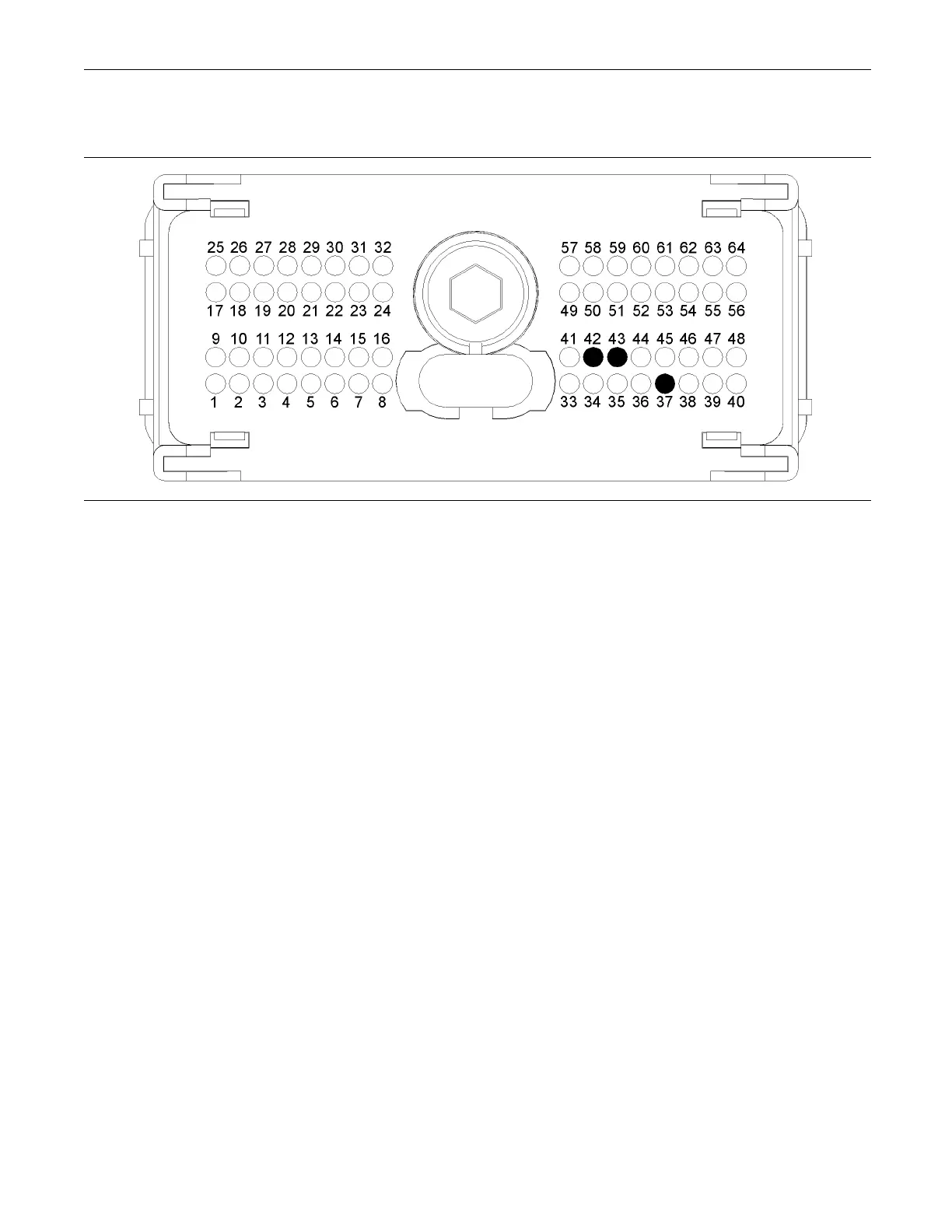
Illustration 51
Typical view of the P2 pin locations on the temperature sensor
(37) Ground (GND) Intake Manifold Air
Temperature S ensor and Coolant
Temperature Sensor
(42) Signal (SIG) Intake Manifold Air
Temperature Sensor
(43) Signal (SIG) Coolant Tem perature
Sensor
A. Thoroughly inspect ECM engine harness
connector P2 and the suspect sensor connector.
Refer to Troubleshooting, “Electrical Connectors
- Inspect”.
B. Perform a 45 N (10 lb) pull test on each of the
wires in the sensor connector and the ECM
connector that are associated with the active
diagnostic code.
Refer to illustration 51.
C. Verify that the latch tab of the connector is
correctly latched. Also verify that the latch tab of
the connector has returned to the fully latching
position.
D. Check the screw for the ECM connector for the
correcttorqueof5.0N·m(44lbin).
E. Check the harness for abrasions and for pinch
points from the sensor to the ECM.
Expected Result:
All connectors, pins, and sockets should be
completely coupled and/or inserted. The harness
should be free of corrosion, abrasion, and pinch
points.
Results:
•
OK – Proceed to Test Step 3.
•
Not OK – Repair the connectors or the harness
and/or replace the connectors or the harness.
Ensure that all of the seals are correctly in place
and ensure that the connectors are completely
coupled. Clear all inactive diagnostic codes. Verify
that the repair has eliminated the fault. Proceed to
Test Step 3 if the fault has not been eliminated.
Test Step 3. Verify That The Diagnostic
Code Is Still Active
A. Turn the keyswitch to the ON position.
Note: Wait at least 10 seconds for activation of the
diagnostic codes.
B. Access the “Active Diagnostic Code” screen on
the electronic service tool and check for active
diagnostic codes.
C. Determine if the fault is related to an “Voltage
Above Normal” diagnostic code or a “Voltage
Below Normal” diagnostic code.
Expected Result:
A “Voltage Below Normal” diagnostic code or an
“Voltage Above Normal” diagnostic code is active.