156 KENR6933
Troubleshooting Section
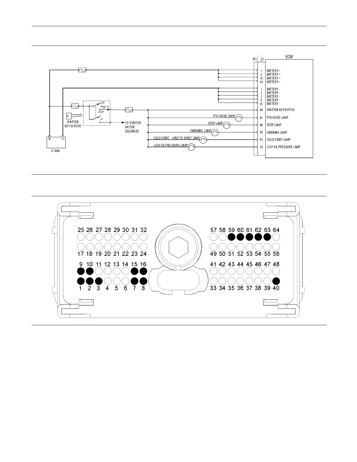
g01336446
Illustration 57
Typical schematic of the indicator lamp circuit
g01176466
Illustration 58
Typical example of the P1 OEM connec tor pin locations
(1) Ground
(2) Ground
(3) Ground
(9) Ground
(10) Ground
(7) Battery+
(8) Battery+
(15) Battery+
(16) Battery+
(40) Keyswitch
(59) Warning lamp
(60) Stop lamp
(61) PTO lamp
(62) Low oil pressure lamp
(63) Cold s tart lamp
Test Step 1. Insp ect Electrical Connectors
and Wiring
A. Turn the keyswitch to the OFF position.
B. Thoroughly inspect P1 OEM connector and the
lamp connections. Refer to Troubleshooting,
“Electrical Connectors - Inspect” for details.
C. Perform a 45 N (10 lb) pull test on each of
the wires in the customer connector and the
Electronic Control Module (ECM) connector that is
associated with the diagnostic lamp.
D. Check the screw for the P1 OEM connector for the
correct torque of 5.0 N·m (44 lb in).