KENR6933 25
Troubleshooting Section
Removal and Installation of the
Harness Connector Termin als
Terminal Removal
Table 7
Required Tools
Part Number Part Description Qty
27610285 Removal Tool 1
g01201559
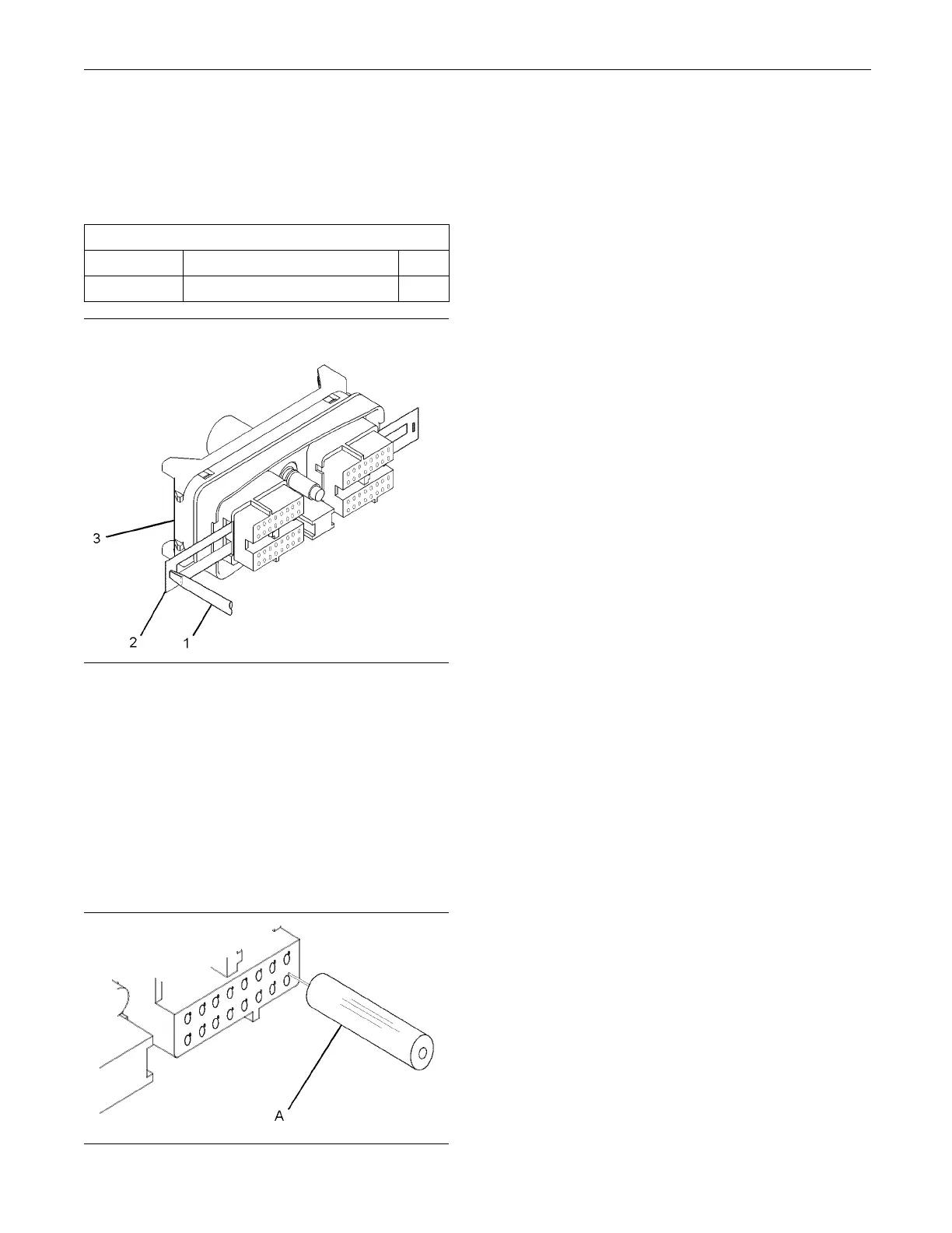
Illustration 11
Removal of Terminal Position A ssurance C omponen ts
1. Remove the connector from the ECM. Refer to
Disassembly and Assembly, “Electronic Control
Module - Remove and Install”.
2. Use a screwdriver that has a flat blade (1) to
remove the two terminal position assurance
components (2) from the connector (3).
Note: Do not use the removal tool to remove the
terminal position assurance components.
g01201632
Illustration 12
Removal Tool
3. Insert the removal tool into the hole that is
adjacent to the
terminal in order to release the
locking device.
Note: Make sur
e that the tool stays perpendicular to
the face of the connector.
4. Hold the tool i
n position and gently pull the wire in
order to remove the terminal from the rear of the
connector (3).
5. Remove the removal tool from the face of the
connector (3).
Note: If a terminal must be replaced, part number
28170085 must be used.
Terminal Insertion
1. Push the term
inal into the rear of the connector (3)
until the terminal engages with the locking device.
2. Gently pull o
n the wire in order to make sure that
the terminal is retained by the locking device.
3. Install the
two terminal position assurance
components (2) into the sides of the connector (3).
4. Connect the
connector to the ECM. Refer to
Disassembly and Assembly, “Electronic Control
Module - Remove and Install”.