Table 67
Troubleshooting Test Steps
Values Results
6. Transfer Pump Inlet Regulator (TPIR) Flow Test
Refer to Illustration 45 .
A. Disconnect the TPIR return line from the drain port on the
TPIR. Install a suitable blanking cap on the open port in the
TPIR return line.
B. Connect a temporary drain line to the drain port on the TPIR.
C. Place the end of the temporary drain line into a suitable cali-
brated container.
D. With the isolator switch in the ON position but the engine not
running, use a suitable multimeter to measure the input voltage
to the EFLP. Record the reading.
E. With the isolator switch in the ON position but the engine not
running, measure the fuel flow from the temporary drain line.
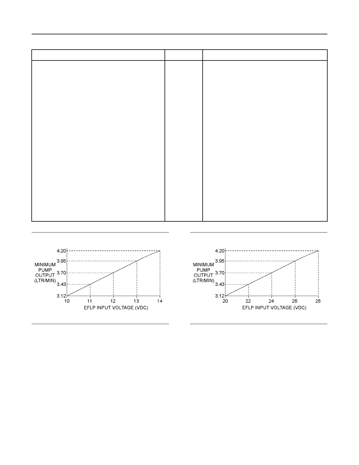
F. Refer to Illustration 46 or 47 for the minimum acceptable flow
rate.
G. Remove the temporary drain line from the drain port on the
TPIR. Connect the TPIR return line to the TPIR.
TPIR flow rate Result: The fuel flow is greater than the minimum limit.
Proceed to Test Step 8.
Result: The fuel flow is less than the minimum limit.
Proceed to Test Step 7.
Illustration 48 g02527498
Minimum EFLP flow rate in a 12 VDC system
Illustration 49 g02527518
Minimum EFLP flow rate in a 24 VDC system
136 UENR4469-36
Symptom Troubleshooting
Copyright of Perkins Engine Company Limited. NOT FOR REPRINTING OR RESALE