permaPRO-8-
4. Mounting and Assembly of the Lubrication System
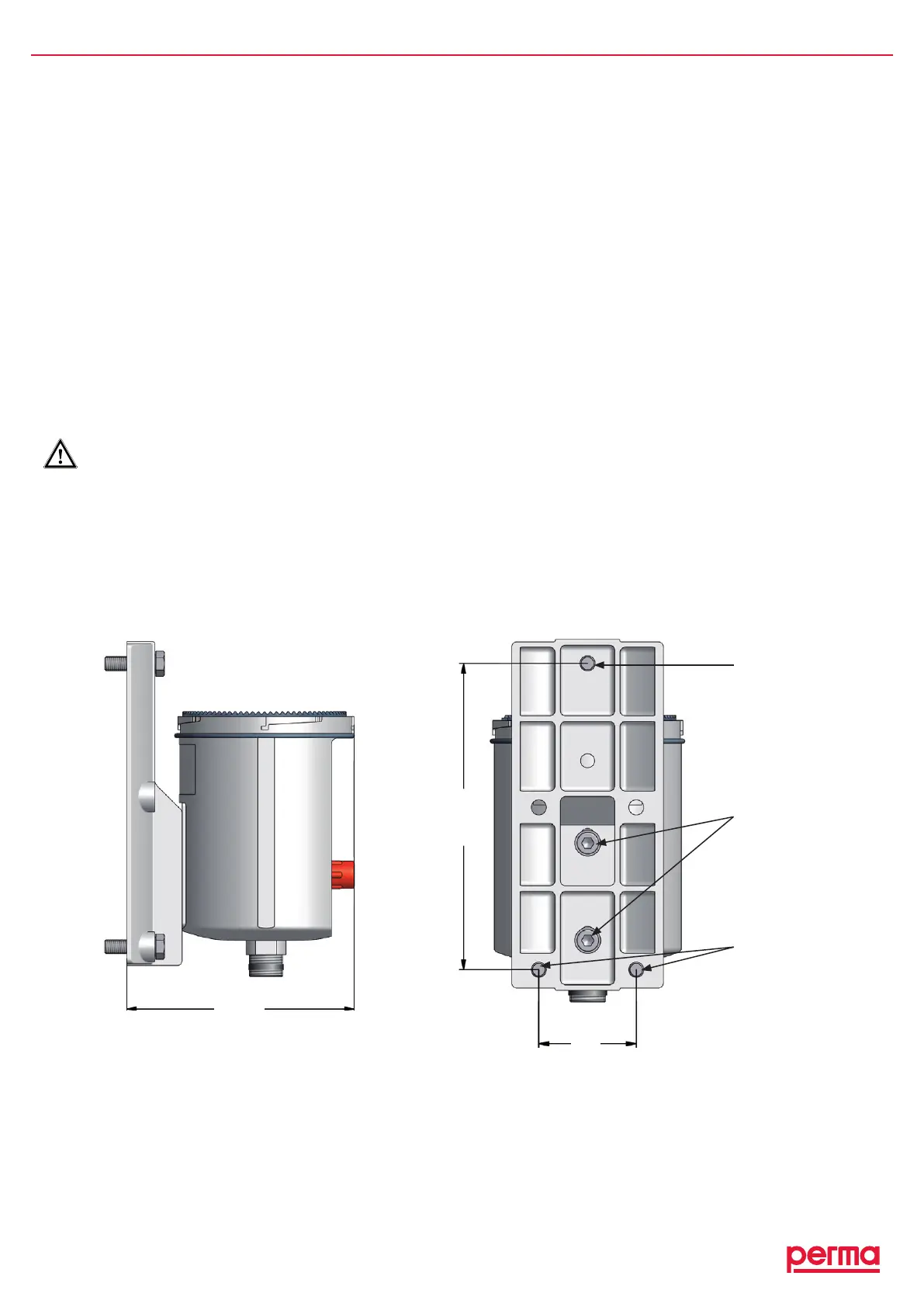
4.1 Mounting the Drive Unit onto a Fixing Device for Wall-Mounting
♦ Attachthesuppliedmountingdevicetothedriveunitusingthetwoenclosedhexheadbolts(M6x16)and
thetwowashers.
♦ Screwthemountingdevicewiththedriveunitontoasupportofyoursystem.
Theboringtemplateofthethreemountingscrews(141.5x45)canbeseenbelowingure3oronthe
templatethatisincluded.YouhavetouseatleastthreehexagonscrewsM6x25(e.g.onmetalground).
♦ Beforeyouconnecttheoutletofthedriveunittothelubricanttube,youhavetomakesurethatthe
lubricationpointsandthecompletelubricanttubeispre-lubricatedwiththesamelubricantthatiscontained
inthePROLCunit.Forthat,perma-tecoffersa400glubricationcartridgeformanually-operatedgrease
presseswiththerequestedlubricant.
♦ Connectthelubricanttube(connectionG3/8)totheoutletofthedriveunitandinstallthetubecorrectly
betweentheoutletandthelubricationpoint.Thelubricanttubemustnotbelongerthanvemeters.
Make sure that you assemble the connections and lubricant tubes correctly and tightly to avoid
possible leakage.
141.5
45
gure3
2hexheadbolts
M6x16,maximum
torque3Nm(supplied
forattachingthe
permaPROtothe
mountingdevice)
Hexagonscrews
M6x25
(forwallmounting
onmetal)
2hexagonscrews
M6x25
(forwallmounting
onmetal)
113