permaPROC -11-
%Vol.
LC 500
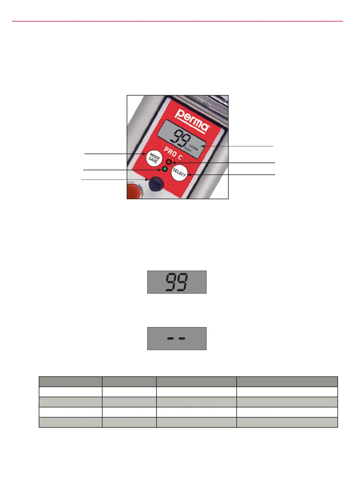
5. Display and Control Elements of the Lubrication System
5.1 Display Elements
TheoperatingstatusofthelubricatorcanbedeterminedviathegreenortheredLEDandviathedisplayatthe
controlunit(refertogure8)ofthepermaPROC.
ThepermaPROCoffersamenu-guidedsetting.Changesofthesettingsareshownonthedisplay.Error
messages,e.g.incasethepressureinthelubricanttubegetstoohigh,arealsoindicatedonthedisplay.
5.2 Function Indication on the Display
ThedisplayislocatedonthecontrolunitofthepermaPROC(refertogure8,chapter5.1).
Thedisplayshowssettings,operatingconditionsanderrormessagesofthelubricator.
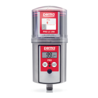
Incaseofanerrorfreeoperationofthelubricationsystem,thedisplayshowstheremainingvolumeofthe
mountedPROLCunitinpercentvolume(%Vol.).Figure9showsanexampleofthedisplayedinformation
ifthePROLCunit500isnewandfull.
gure8
MODE
SAVE
push-button
LCD
redLED
SELECT
push-button
greenLED
Connectorfor
distributorMP-6
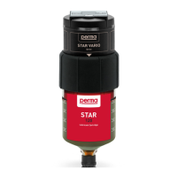
The display cannot be switched off by the operator. If the lubrication system is switched off, the display
will always show two lines (see gure 10 below).
gure9
gure10
5.3 Function Indication via the LEDs
LED Signal Signal Length Explanation
green ash every10seconds operation(OK)
red ash every3seconds error/malfunction
greenandred ash every3seconds PROLCunitempty
green light permanently Lubricatorisdischarging
chart3
5.4 Function Indication via the Connected Control System
Theconnectedcontrolsystemofyourequipmentcanonlyindicatethatthelubricatorisworking,orthatthereis
amalfunction.IfthepermaPROCisworking,thecontrolsystemreceivesa“High”signalandforamalfunctiona
“Low”signal.