perma PRO -11-
5. Display and Control Elements of the Lubrication System
5.1 Display Elements
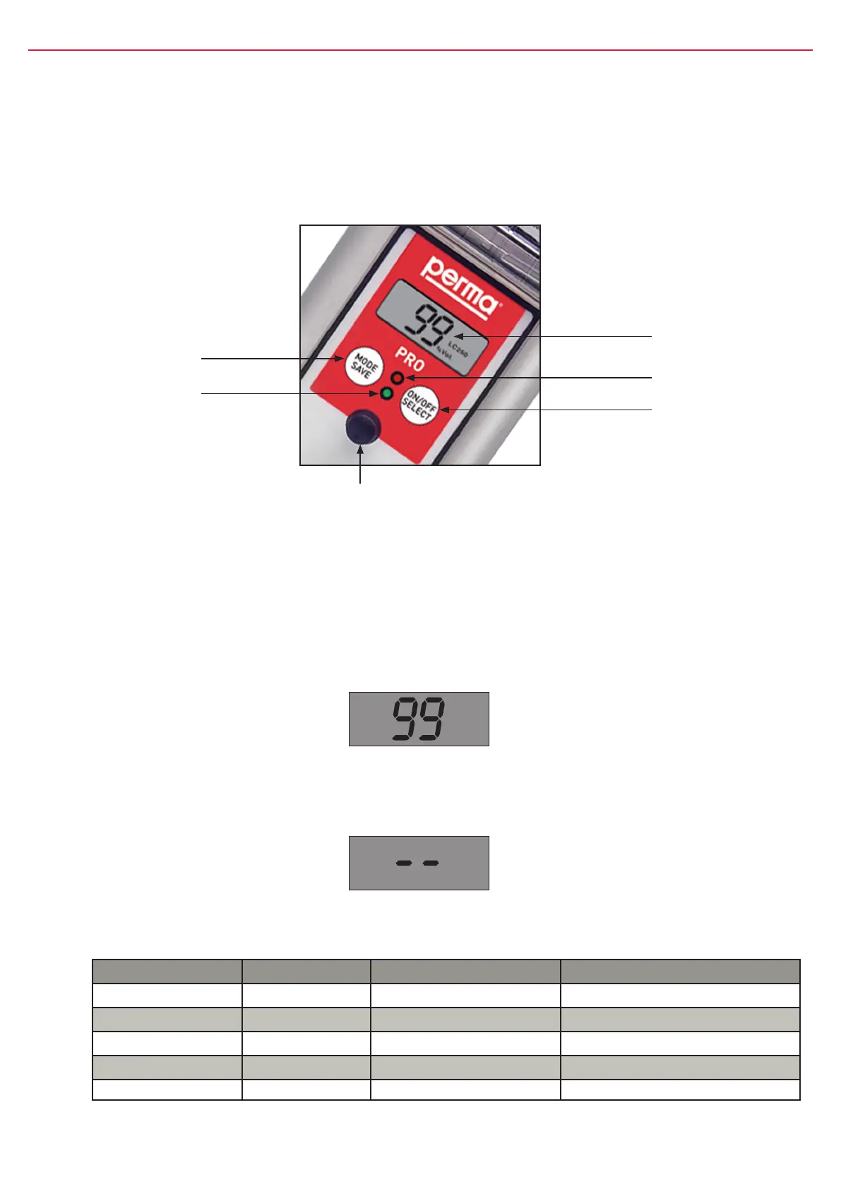
TheoperatingstatusofthelubricatorcanbedeterminedviathegreenortheredLEDandviathedisplay
atthecontrolunit(refertogure8)ofthepermaPRO.
ThepermaPROoffersamenu-guidedsetting.Changesofthesettingsareshownonthedisplay.Error
messages,e.g.incasethepressureinthelubricanttubegetstoohigh,arealsoindicatedonthedisplay.
5.2 Function Indication on the Display
ThedisplayislocatedonthecontrolunitofthepermaPRO(refertogure8,chapter5.1).
Thedisplayshowssettings,operatingconditionsanderrormessagesofthelubricator.
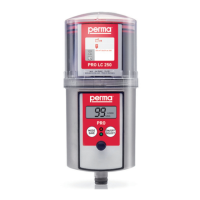
Incaseofanerrorfreeoperationofthelubricationsystem,thedisplayshowstheremainingvolumeofthe
mountedPROLCunitinpercentvolume(%Vol.).Figure9showsanexampleofthedisplayedinformation
ifthePROLC500-unitisnewandfull.
push-button
MODE
SAVE
LCD
RedLED
push-button
ON/OFF
SELECT
GreenLED
Connectorfor
distributorMP-6
gure8
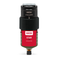
The display cannot be switched off by the operator. If the lubrication system is switched off, the display
will always show two lines (see gure 10 below).
%Vol.
LC 500
gure9
gure10
5.3 Function Indication via the LEDs
LED Signal Signal Length Explanation
green ash every10seconds operation(OK)
red ash every3seconds error/malfunction
greenandred ash every3seconds PROLCunitempty
green light permanently Lubricatorisdischarging
greenandred none none Lubricatorswitchedofforbatterylow
chart2