permaPROC-10-
c)
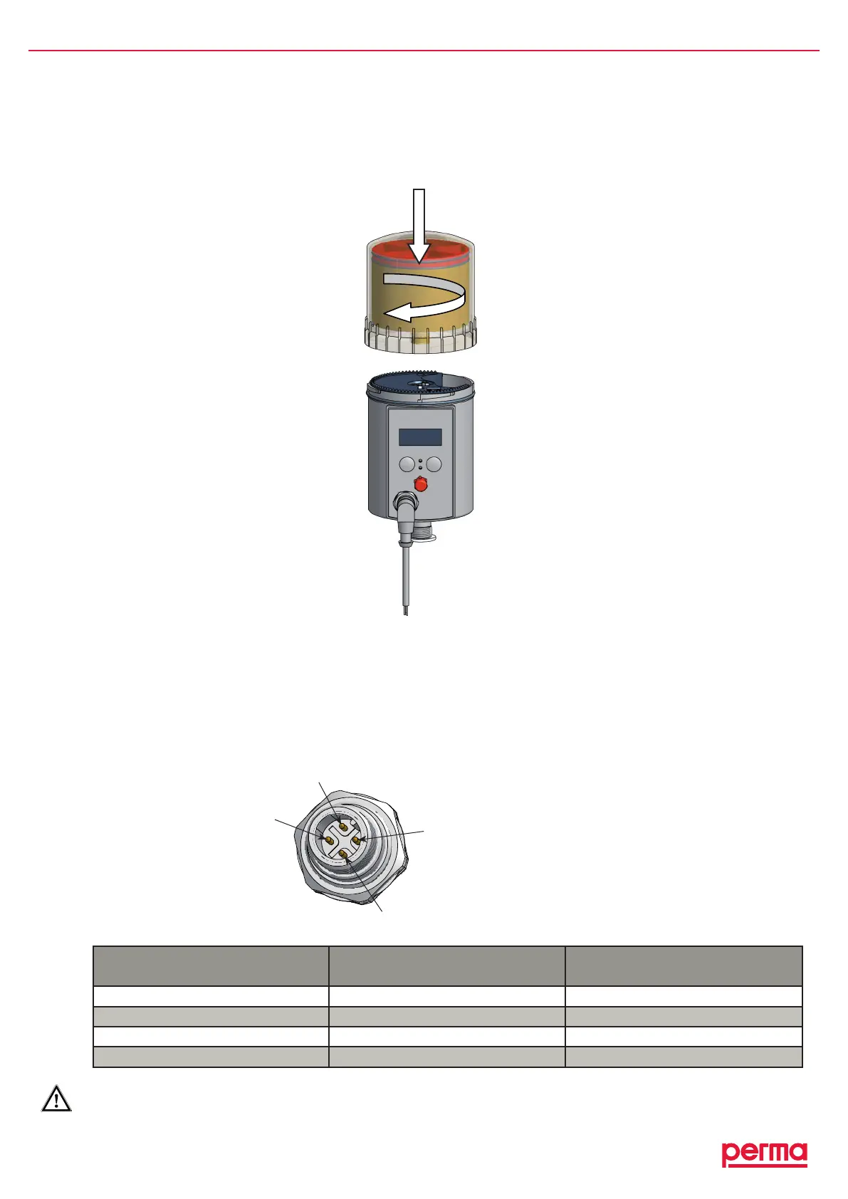
♦ PlacethePROLCunitwithitsprotectioncoveronthedrive-unit.Makesurethatthecatchlocksandthatthe
teethofthePROLCunitandthedriveunitinterlock(refertogure6).
♦ Turnthecoverclockwiseuntilthebayonetcatchlocks.
4.3 Connect the Connecting Cable to the Lubricator
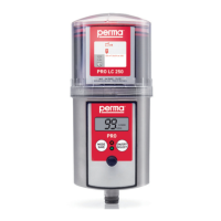
♦ Connectthefourstrandsoftheconnectingcabletothecontrolsystem(e.g.aPLC)ofyourequipmentand
payattentiontothepinassignmentoftheconnectoronthelubricator(refertochart2andgure7).
♦ Insulatetheconnectedstrandscorrectly.
♦ Insertthe4-poleconnectingcableintotheconnectorofthelubricator(refertogure6).
♦ Screwtighttheconnectorsocketoftheconnectingtotheconnectorofthelubricator.
Pin no. of the connector
on the lubricator
Strand color of the
standard cable
Function
1 brown Notassigned
2 white Malfunction*
3 blue Ground
4 black Voltage(15Vto30V–DC)
chart2
*Errorsignalislow-active!(negativelogic)
gure7
Pinassignmentofthe
connectoronthelubricator
1
2
4
3
gure6