Mixing Pump PFT G4
Maintenance
2007-09-05 67
Pos: 8.27 /KN2006-Pr ojekte/Knauf/W artung/Mischpumpe PFT G4/1.1. 1 Drücke und Einstell werte prüfen @ 36\mod_11773 48092466_293361. doc @ 446098
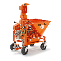
8.4.5 Check pressure and set values
Pressure reducer valve
Fig. 70: Pressure reducer valve
Adjust a pressure of 1.9 bar (27.6 psi) at maximum passage on
the pressure reducer valve (Fig. 70).
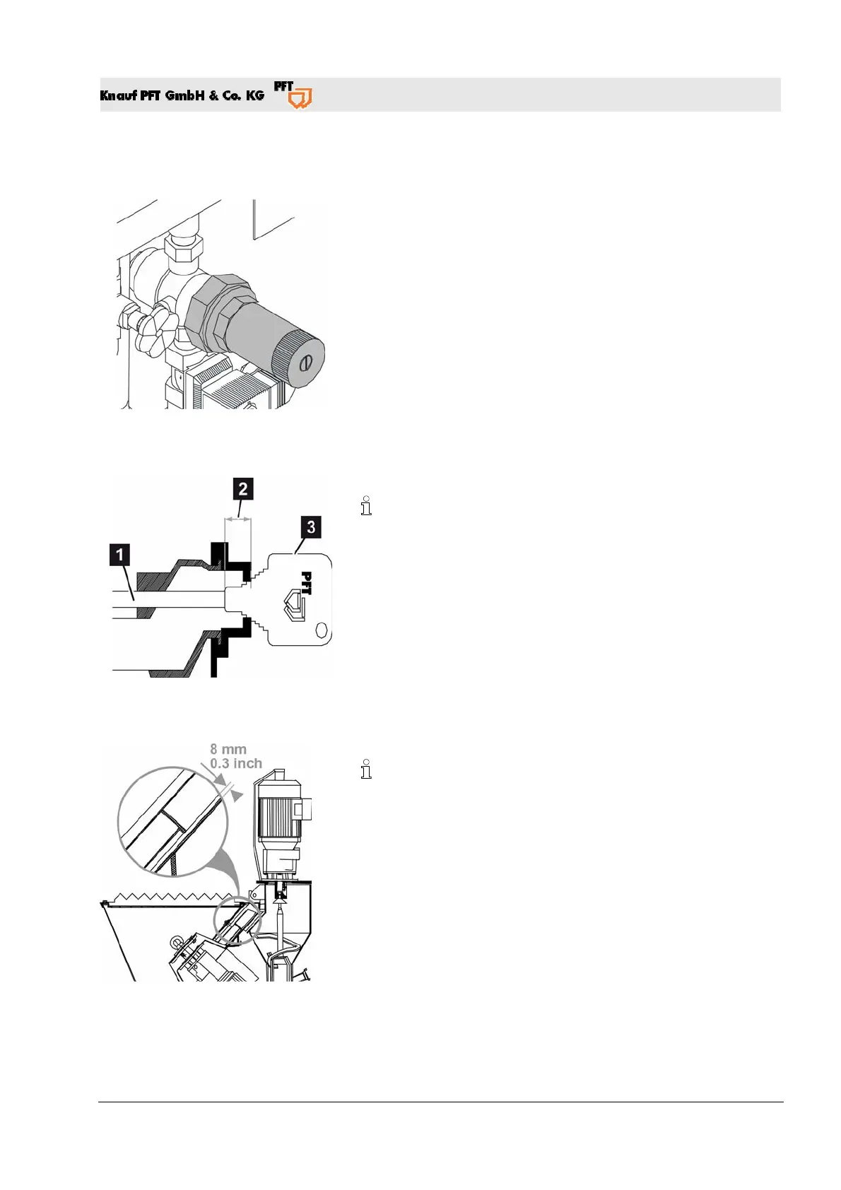
Adjust the air nozzle pipe clearance
Fig. 71: Air nozzle pipe clearance
Adjust the air nozzle pipe (Fig. 71/2) clearance with the supplied
gauge (
Fig. 71/3).
The distance between the air nozzle pipe and the plaster nozzle
must correspond to the hole diameter of the plaster nozzle; for
example: 14 mm (0.55 inch) fine plaster nozzle = distance of
14 mm (0.55 inch).
Cellular wheel
Fig. 72: Cellular wheel
Distance from cellular wheel to hopper floor (Fig. 72):
Factory set at approximately 8 mm (0.3 inch).
Rule of thumb: 1.5 times the diameter of the largest grain of
factory dry-mix mortar. If needed the cellular wheel spacer disk
(to be order under the item no. 20 10 19 00) can be installed for
coarse grain plaster.
Pos: 8.28 /KN2006-SM/nL---------- Abschnittsende ---------- @ 8\mod_1141997892953_0.doc @ 293763