Mechanical Instructions
GB 19L01.1A 4.
4. Mechanical Instructions
Index:
1. Rear Cover Removal
2. Service Position Main Panel
3. Side I/O Panel Removal
4. Rear Cover Mounting
Note:
Figures can deviate slightly from the actual situation, due to
different set executions.
4.1 Rear Cover Removal
1. Remove all fixation screws of the rear cover.
2. Now pull the rear cover backward to remove it.
4.2 Service Position Main Panel
There are two configurations. With and without panel
bracket. Both have a different service position:
Main panel without bracket.
1. Disconnect the strain relief of the AC power cord.
2. Remove the main panel, by pushing the two center clips
outward [1]. At the same time, pull the panel away from
the CRT [2].
3. Disconnect the degaussing coil by removing the cable
from (red) connector 0201.
4. Turn the panel 90 degrees counter clockwise [3].
5. Flip the panel 90 degrees [4], with the components
towards the CRT.
6. Turn the panel with the rear I/O towards the CRT [5].
7. Slide the metal heatsink (near the mains transformer
5520) underneath the right chassis bracket, so the panel
is secured [6].
Figure 4-1
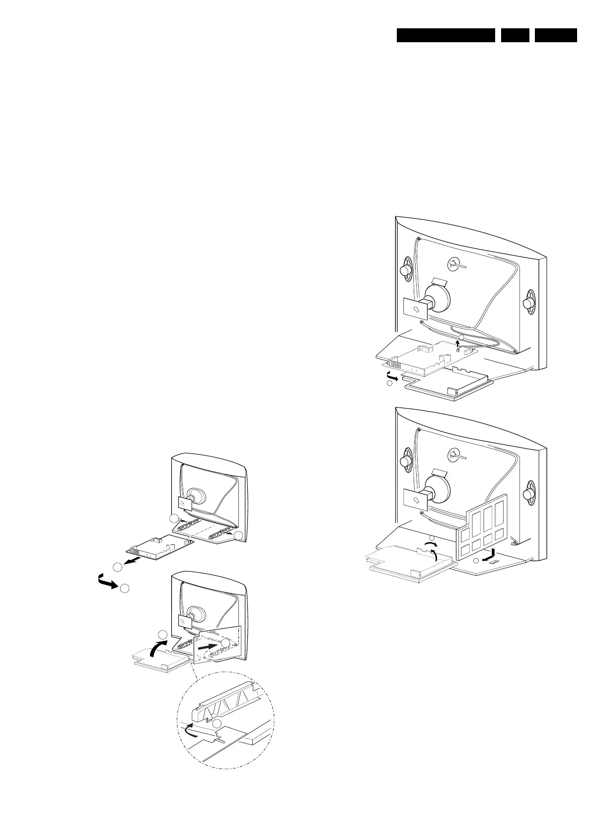
Main panel with bracket.
1. Disconnect the strain relief of the AC power cord.
2. Disconnect the degaussing coil by removing the cable
from (red) connector 0201 [1].
3. Remove the panel bracket from the bottom tray, by
pulling it backward [2].
4. Turn the chassis tray 90 degrees counter clockwise.
5. Move the panel somewhat to the left and flip it 90
degrees [3], with the components towards the CRT.
6. Turn the panel with the rear I/O towards the CRT.
7. Place the hook of the tray in the fixation hole of the
cabinet bottom [4] and secure it.
Figure 4-2
B
1
A
CL 16532016_007.ai
040401
3
6
4
5
1
1
2
A
CL 16532016_009.eps
220501
B
4
3
2
1