Mechanical Instructions
GB 20 L01.1A4.
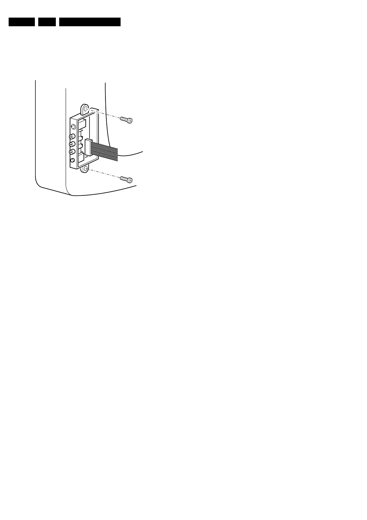
4.3 Side I/O Panel Removal
1. Remove the complete Side I/O assembly after
unscrewing the two fixation screws [1].
2. Release the 2 fixation clamps [2] and lift the board out of
the bracket.
Figure 4-3
4.4 Rear Cover Mounting
Before you mount the rear cover, perform the following
checks:
1. Check whether the AC power cord is mounted correctly
in its guiding brackets.
2. Replace the strain relief of the AC power cord into the
cabinet.
3. Check whether all cables are replaced in their original
position.
CL 06532012_004.eps
030200