CAPAROC system
34 / 66
PHOENIX CONTACT 109745_en_01
6.2 Connecting loads
Switching off the channel Before connecting the load, make sure that the relevant channel on which the load is to be
operated is switched off (LED is off).
Connecting the load Connect the load via the load output of the relevant circuit breaker module as described in
Section 5, “Connecting or removing cables”.
Switching on the channel Then start the channel up again by pressing the channel LED (green LED).
6.3 Diagnostic and status indicators
6.3.1 Indicators on the power module
The power modules have status LEDs to indicate the current operating state.
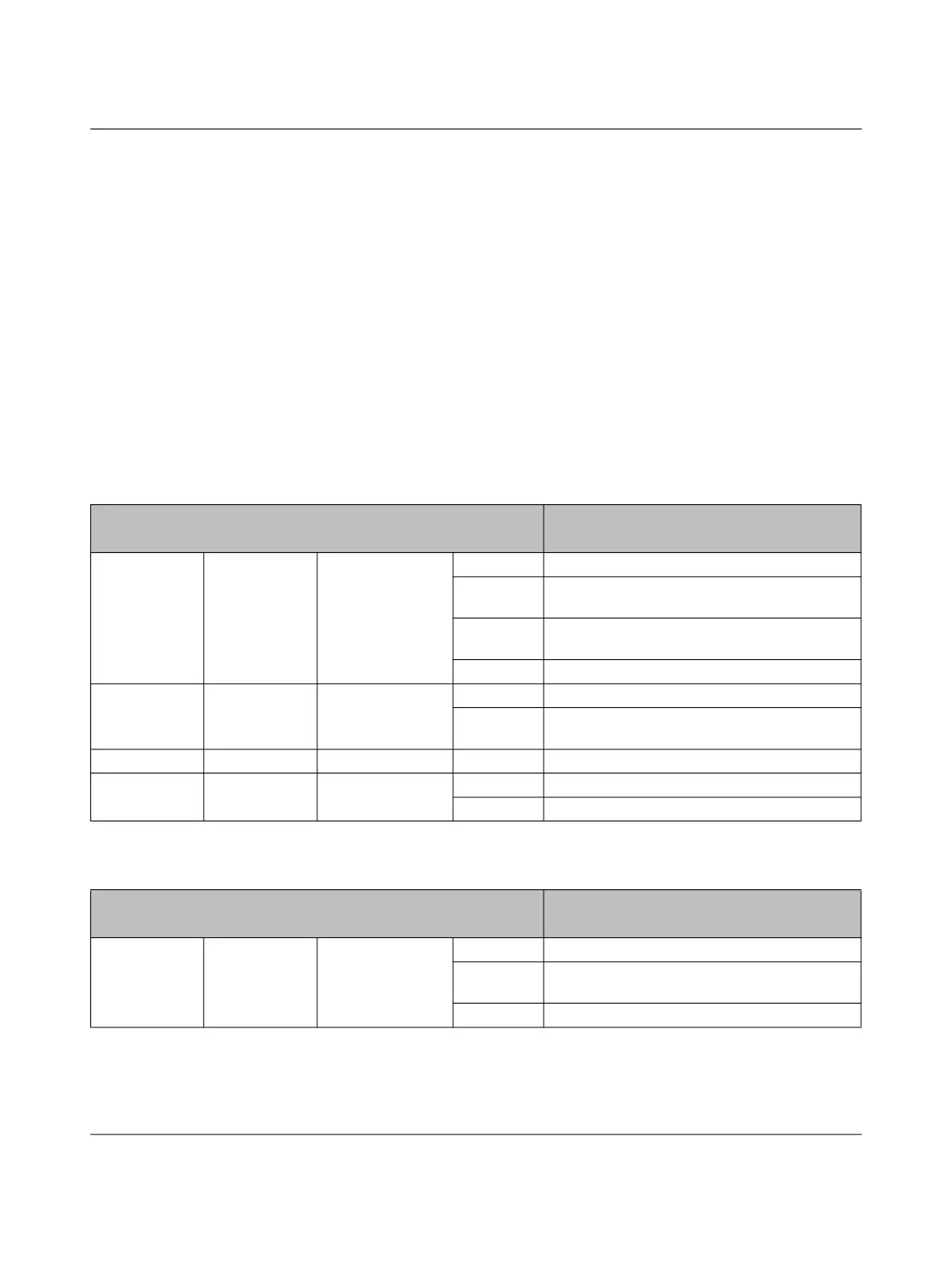
Table 6-3 Visual signaling of the PROFINET power module (PM PN)
LED Description
Designation Color Meaning State
PWR Green/yel-
low/red
Voltage indicator Green on Operating voltage present
Red on Operating voltage outside the nominal voltage
range
Flashing
yellow
Firmware update is in progress
Off Operating voltage not present
BF Red Bus error On No bus connection
Flashing Bus connection present, no connection to a
PROFINET controller
SF Red System error On PROFINET diagnostic data available
RDY Green Ready On Device is ready for operation
Off Device is not ready for operation
Table 6-4 Visual signaling of the power module status-reset (PM S-R)
LED Description
Designation Color Meaning State
PWR Green/yel-
low/red
Voltage indicator Green on Operating voltage present
Red on Operating voltage outside the nominal voltage
range
Off Operating voltage not present
 Loading...