CAPAROC system
8 / 66
PHOENIX CONTACT 109745_en_01
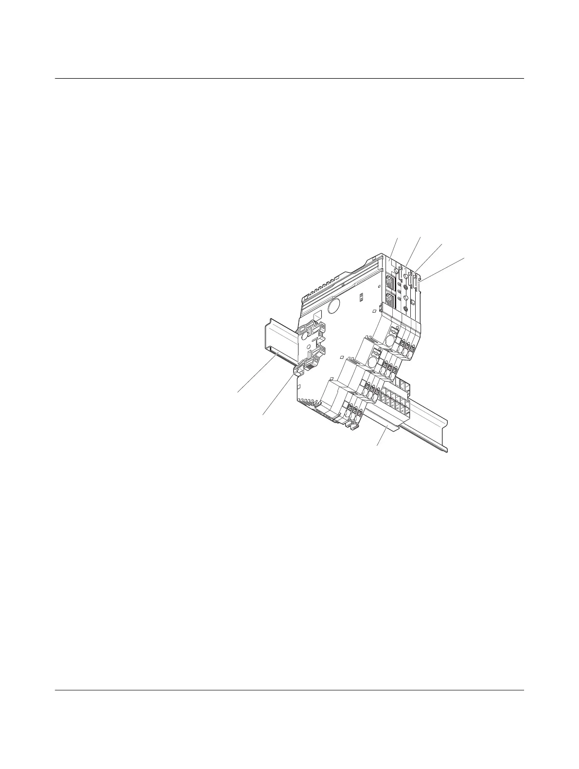
2.2 Structure of the CAPAROC system
A CAPAROC system consists of individual modules, which are snapped onto a DIN rail via
a current rail.
The power module forms the head of the station. The circuit breaker modules are connected
to the right of it.
The connection between the power module and the individual CAPAROC modules is estab-
lished via the side bus connectors. The internal CAPAROC bus is formed automatically
when the various CAPAROC modules are snapped on.
Figure 2-1 Example of a CAPAROC system
1 DIN rail
2 End bracket
3 Power module
4 2-channel 2 - 10 A circuit breaker
5 1-channel 1 - 10 A circuit breaker
6 Potential distribution module
7 Current rail
 Loading...