Appendix for document lists
109745_en_01 PHOENIX CONTACT 61 / 66
A Appendix for document lists
A 1 List of figures
Section 2
Figure 2-1: Example of a CAPAROC system .......................................................... 8
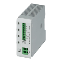
Figure 2-2: PM PN and PM S-R power modules ................................................... 10
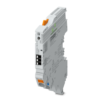
Figure 2-3: Example: 1-channel, 2-channel, and 4-channel circuit breaker
modules .............................................................................................. 11
Figure 2-4: Example: CR 20 and CR EXT8 current rails ........................................ 12
Figure 2-5: Housing versions ................................................................................ 13
Figure 2-6: Design of CAPAROC PM PN .............................................................. 14
Figure 2-7: Dimensional drawing of CAPAROC PM PN ........................................ 14
Figure 2-8: Design of CAPAROC PM S-R ............................................................. 15
Figure 2-9: Dimensional drawing of CAPAROC PM S-R ....................................... 15
Figure 2-10: Design of CAPAROC E1 ... ................................................................. 16
Figure 2-11: Dimensional drawing of CAPAROC E1 ... ........................................... 16
Figure 2-12: Design of CAPAROC E2 ... ................................................................. 17
Figure 2-13: Dimensional drawing of CAPAROC E2 ... ........................................... 17
Figure 2-14: Design of CAPAROC E4 ... ................................................................. 18
Figure 2-15: Dimensional drawing of CAPAROC E4 ... ........................................... 18
Figure 2-16: Design of CAPAROC PD 0V ............................................................... 19
Figure 2-17: Dimensional drawing of CAPAROC PD 0V ......................................... 19
Section 4
Figure 4-1: Placing and removing the module vertically ........................................ 23
Figure 4-2: Snapping on the modules ................................................................... 25
Figure 4-3: Removing the current rail .................................................................... 26
Figure 4-4: Mounting distances for the CAPAROC system ................................... 27
Section 5
Figure 5-1: Connecting the CAPAROC power supply ........................................... 30
Section 6
Figure 6-1: Flow chart for initial startup of CAPAROC PROFINET ........................ 36
 Loading...