Chapter. 2 Setup
2.2.6. RS-422 Serial Control
The system supports serial control via an RS-422 connection through the "KEYPAD" connector.
By setting the [STATUS OUT] menu to ON, the system status can be output via the serial
connection.
For details, check the command list.
Serial control commands are available as separate list of commands. Please contact Photron or the
dealer where the system was purchased regarding the command list.
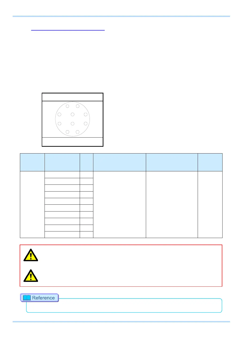
A cable is also not offered as an accessory. When using RS-422 control, construct a cable using the
pin diagram below for reference.
ECG.2B.310.CLN
Connector
Name
Signal Name
Pin
No.
Camera Body Connector
Model Name
Cable Connector Model
Name
Input
Connector
KEYPAD
ECG.2B.310.CLN
(LEMO)
S22L0C-P10MJG0-820S
(ODU)
Not
Specified
When using the connector pins directly, refer to the chart above and ensure the wiring is correct.
Incorrect wiring can cause malfunction.
The voltage on pin 10 (+12V OUT) is used to power the remote controller, do not use it for other
purposes.
•
For inquires related to our product, refer to “7.1. Contact Information”, page 106.
14
 Loading...