Chapter. 3 Recording
3.18. Using External Triggers
With the system, you can record by receiving various trigger signals matched to the recording
application. The trigger signals that can be used on the system are explained here, along with a
description of how to use them.
3.18.1. Inputting an External Trigger Signal
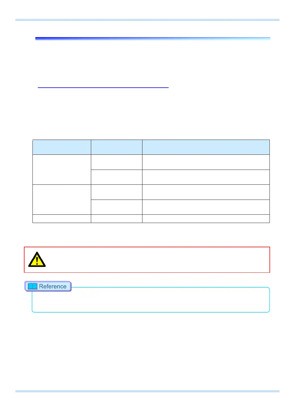
The external trigger signals that can be used with the system and their input system are listed below.
External trigger signal input settings are also made by selecting [SYNC IN/OUT] from the menu and
[TRIG TTL IN] or [GENERAL IN] from the submenu.
The signals input from the TRIG TTL IN and GENERAL IN connectors are explained in section
"2.2.7. I/O Port Connector".
Connector Name
Menu Signal
TRIG TTL IN
TRIG POS
FET Input 0V - +12V (H level +2.5V to +12V), Positive
TRIG NEG
FET Input 0V - +12V (H level +2.5V to +12V),
GENERAL IN
TRIG POS
FET Input 0V - +12V (H level +2.5V to +12V), Positive
TRIG NEG
FET Input 0V - +12V (H level +2.5V to +12V),
Set the signal type to be input to GENELAL IN from the menu in advance.
Use caution not to input more than specified voltage or current to the TRIG TTL IN and
GENERAL IN trigger signal inputs as there is a risk of damage to the equipment.
•
For the setting method of the signal inputted into GENERAL IN, refer to “3.20.1. GENERAL IN
Signal Settings”, page 63.
52
 Loading...