3.20. GENERAL Signal Settings
3.20.1. GENERAL IN Signal Settings
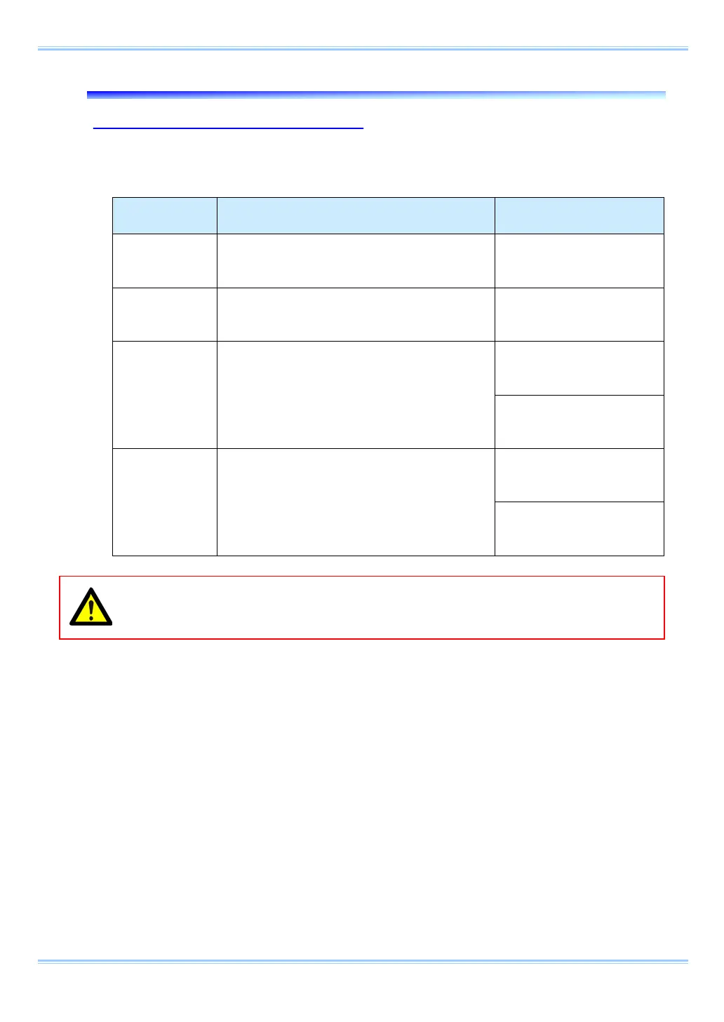
Details of the signals output from the GENERAL OUT connector explained in section “3.17. Contact
Information” are shown in the chart below.
Menu Display Contents
Signal
(Input Signal Conditions)
TRIG POS Inputs a positive polarity trigger signal.
FET Input 0V - +12V (H
level +2.5V to +12V),
TRIG NEG Inputs a negative polarity trigger signal.
FET Input 0V - +12V (H
level +2.5V to +12V),
READY POS
Inputs a positive polarity READY signal.
READY ON/OFF is switched by a pulse input.
FET Input 0V - +12V (H
level +2.5V to +12V),
FET Input 0V - +12V (H
level +2.5V to +12V,
READY NEG
Inputs a negative polarity READY signal.
READY ON/OFF is switched by a pulse input.
FET Input 0V - +12V (H
level +2.5V to +12V),
FET Input 0V - +12V (H
level +2.5V to +12V),
When using the camera as a part of a system, verify the characteristics of the input signals
before using them.
63 FASTCAM SA-Z Hardware Manual
 Loading...