TRIG TTL IN
TRIG TTL OUT
TRIG SW IN
SYNC IN
GENERAL IN
GENERAL OUT1
GENERAL OUT2
GENERAL OUT3
IRIG IN
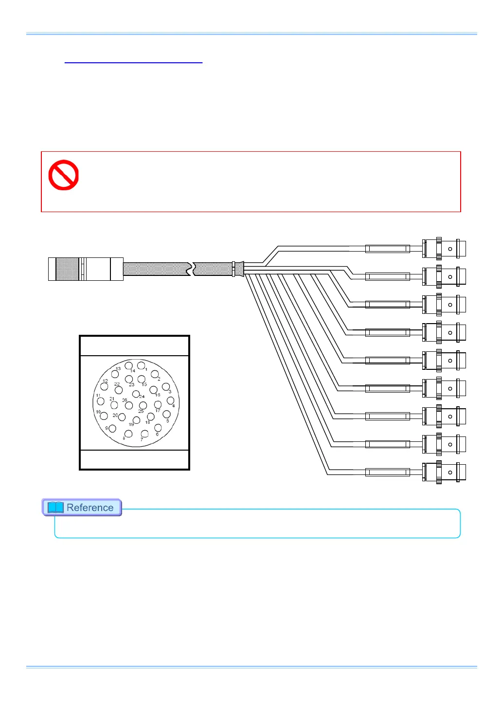
2.2.7. I/O Port Connector
The input/output signal connectors on the system have been bundled into a single connector, the
"I/O PORT" connector, and it is possible to connect to and access each type of signal by using the
specialized multi-connector. By inputting an external trigger or synchronization signal and by
outputting exposure timing or synchronization signal, these signals can be used as a part of the
system.
A signal other than the specified signal must not be input to the various connectors.
Use extreme caution as there is a risk of damage to both devices, the input device and the
•
For the signal which can be inputted, refer to “3.17. Input / Output Signal types”, page 50.
I/O PORT (Camera Body)
ECJ.2B.326.CLD
15 FASTCAM SA-Z Hardware Manual
 Loading...