3.17.5. GENERAL IN Connector
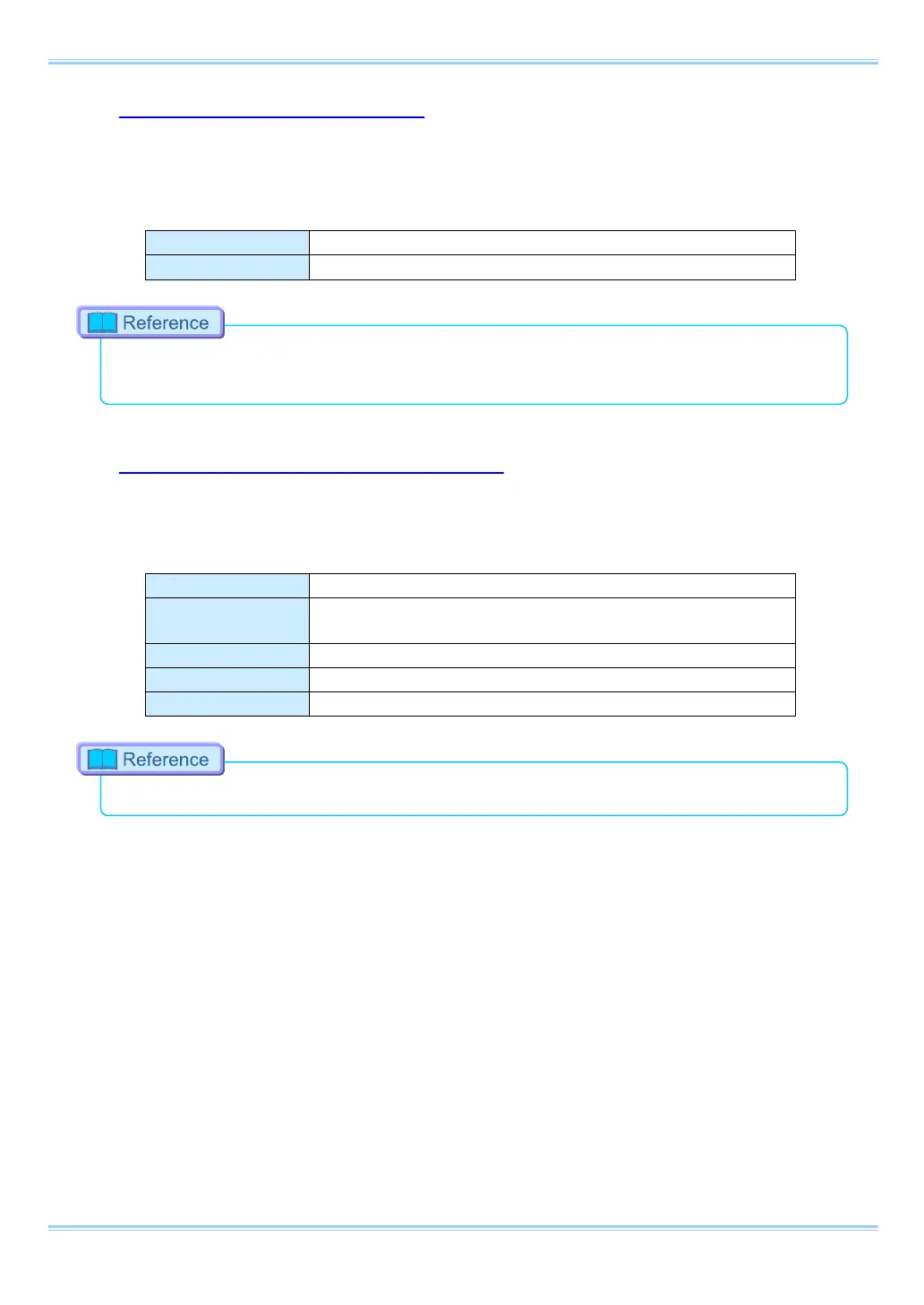
The effect when a signal is input is described below, and can be optionally selected and set.
The input voltage is 0V to +12V (H level +2.5V to +12V), positive or negative polarity, pulse width is
200 ns or greater.
Inputs a TTL trigger signal.
Inputs a change recording ready status signal (READY ON/OFF).
•
To make the setting from the menu, refer to “3.20.1. GENERAL IN Signal Settings”, page 63.
•
To make the setting from PFV, refer to "Photron FASTCAM Viewer User’s Manual".
3.17.6. GENERAL OUT (1, 2, 3) Connector
These are also BNC connectors. The signals below can be changed and output from the menu or
PFV.
(POS: positive polarity, NEG: negative)
Outputs a vertical synchronization signal.
EXPOSE POS/NEG
Outputs the camera's exposure period signal.
* Outputs during both LIVE and recording.
Outputs a signal during recording.
Outputs the trigger signal the camera received.
Outputs a signal that indicates the recording ready state.
•
For details refer to “3.20.2. GENERAL OUT Signal Settings”, page 64.
51 FASTCAM SA-Z Hardware Manual
 Loading...