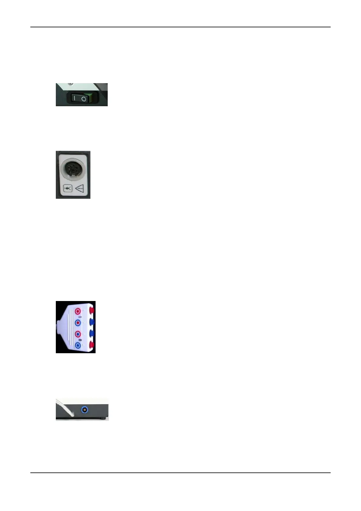
2.7 Power Switch <8>
If you look at the instrument from the front, the Power Switch <8> is on its
left side. By means of this switch, you can switch the instrument on and off.
After switching on, a selftest is automatically carried out by the instrument
(refer to Function Check on page 39).
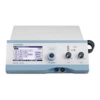
2.8 Patient Lead Connector <9>
The Patient Lead Connector <9> on the rear face of the instrument serves to plug
in the patient lead. Plate electrodes, adhesive electrodes or other types of electrodes
are plugged into the patient lead. The Patient Lead Connector <9> also serves to
connect a PHYSIOVAC-Basic vacuum application instrument (refer to Vacuum Ap-
plication Unit on page 65).
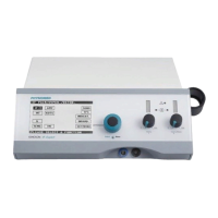
2.8.1 Patient Lead: Mode of Attachment
The colours of the connectors facilitate easy and correct attachment of the electrodes to the two channels
and to their polarity:
• The colour of the inner channel symbolizes the colour of the electrode lead: red = channel I, blue =
channel II
• The colour of the outer channel symbolizes the colour of the connector: red = anode (+), blue = cath-
ode (-)
anode (+) channel I
cathode (-) channel I
anode (+) channel II
cathode (-) channel II
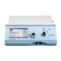
2.9 Ultrasound Lead Connector <10>
The ultrasonic transducer is connected via the Ultrasound Lead Connector <10>
on the right-hand side of the instrument. The ultrasonic transducer is automatically
calibrated when it is plugged in or after the initial selection of the ultrasound menu
after switching on the instrument (refer to Ultrasound Therapy on page 55).
The Ultrasound Lead Connector <10> is clearly marked with a blue ring to pre-
vent any danger of confusion with other sockets.
PHYSIOMED ELEKTROMEDIZIN AG
2 Controls and Indicators
IONOSON-Basic 9