English
18
S
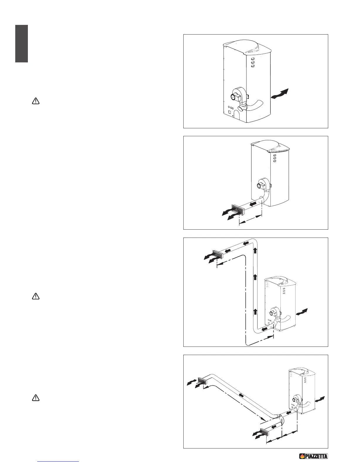
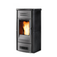
OLUTION 1 - Fig. 28-29:
• The stove is installed in the room which is to be heated, with the
hot air directed to the front only, as when the stove arrives from
the factory (fig. 28). Alternatively the air can flow to the rear by
connecting a 7.5 cm diameter hose to the fan outlet (fig. 29). In
this case the stove heats the room where it is installed by
radiation only, and heats the adjoining room through the
ductwork to the rear.
For the example shown in fig. 29 it is necessary to use an
outlet which is permanently open.
SOLUTION 2 - Fig. 30
• The stove is installed in the room to be heated with the hot air
ducted to the front and also to the rear by installing a Y-element,
thereby allowing the heating of a second room. A 7.5 cm diameter
hose with a maximum length of 4.5 metres is connected to the fan
outlet (fig. 30).
For the example shown in fig. 30 the outlet should be
partially open but never fully closed to avoid overheating.
SOLUTION 3 - Fig. 31:
• Extending the previous solution, with the stove installed in the
room to be heated and the air flow ducted to the front and the
rear, but using a second Y-element at the rear as shown in the
figure. Use a 7.5 cm diameter hose with a maximum total length
of 4.5 metres (fig. 31).
For the example shown in fig. 31, for efficient ducting it is
necessary to use only partially open outlets as shown
DT2030164-00
F
ig. 28