English
19
D
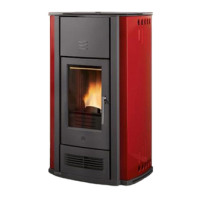
ucting through walls or floors - Fig. 32 / 35
To ensure efficient ducted heat distribution:
1) lag the pipe with insulating material to limit heat loss and
ensure a sufficiently high air temperature;
2) do not exceed the total maximum hose length of 4.5 m.
Below are some examples of how the hose can be installed in walls
or floors (for better performance, lag the hose with suitable
insulating material).
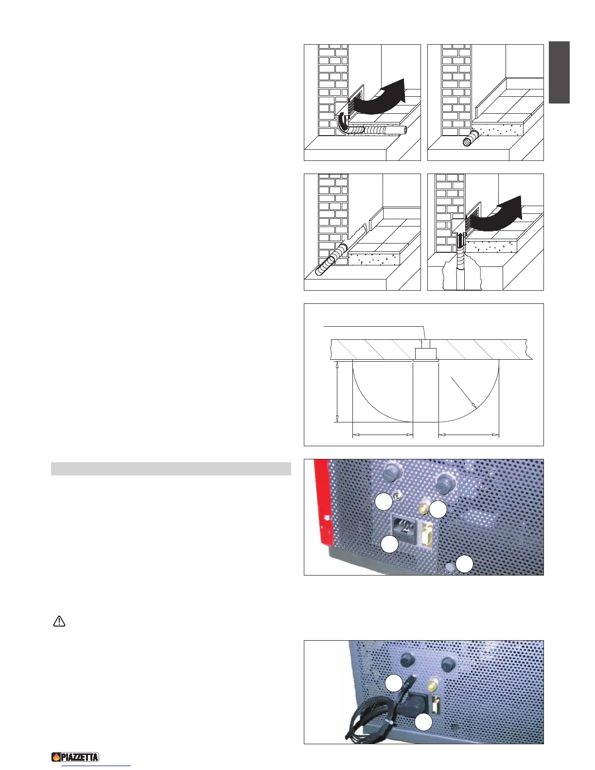
Hot air outlet vent radiation area (mm) - Fig. 36
A safety area must be ensured around the hot air outlet vent within
which there must be no flammable objects (furniture, carpets,
curtains, etc.) or heat sensitive materials (wood, plastic, etc.).
The diagram to the side shows the measurements for this safety
area, which includes 600mm from the upper edge of the vent.
5.2
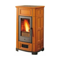
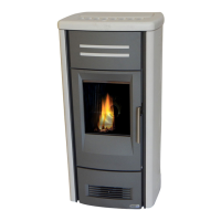
Electrical connection and the room sensor connection - Fig. 37 - 38
• The stove comes with a power cable which must be connected to
a 230v/50Hz (230V/60Hz only for Japan) supply. Connection to
the rear of the stove is shown in fig. 37.
• The power rating is indicated in the paragraph “Technical data” in
this booklet.
• According to law the installation must be earthed and include a
residual current circuit breaker.
• Ensure that in its normal position the power cable does not come
into contact with any heated parts.
Ensure that the electrical socket is accessible also after
installation of the stove.
• When installing the stove, it is necessary to connect the room
sensor (provided) in the correct socket (fig. 37). The sensor can
be positioned as shown in fig. 38, otherwise remove the band and
uncoil the lead and then place the sensor in a spot where a more
accurate room temperature reading can be obtained.