English
20
5
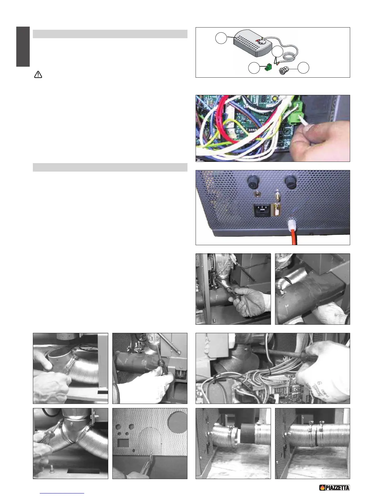
.3 Installing the external thermostat - Fig. 39 / 41
•
To connect the external thermostat use cable of the type 2x0.5mm2 secured with
a PG7 cable gland to be inserted in the relative hole in the rear panel (fig. 41). Only
authorised personnel should carry out this operation.
Installation can be carried out with any type of thermostat but
requires a PG7 cable gland similar to that shown in fig. 39. To
connect the room thermostat to the electronic board, refer to the
wiring diagram.
• When installing, insert the thermostat cable into the PG7 cable gland and
then insert this in the hole in the rear panel (fig. 41). Finally connect the
room thermostat terminal to the two-pin terminal on the electronic board
(fig. 40).
5.4 Installing the Y-element (optional) - Fig. 42 / 50
•
Ducting of heat to adjoining rooms is at the user’s discretion.
The Y-element should be attached to the fan outlet. Proceed as follows:
1. Remove the stove rear panel.
2. Uncoil the hose from the fan outlet by loosening the clip which holds
it in place (fig. 42).
3. Cut off approx. 5 cm hose (fig. 43).
4. Fix the hose to the Y-element using the clip that was previously
loosened (fig. 44).
5. Fix the Y-element to the fan outlet using the screws provided (figs. 45
– 46).
6. Using the hose clip provided, attach a piece of hose to the second
branch of the Y-element, of sufficient length to reach the duct
embedded in the wall (fig. 47).
7. Remove the knockout from the rear panel (fig. 48).
8. Replace the rear panel.
9. Move the stove closer to the wall (fig. 49) and, using the hose clips
provided, fix the hose to the duct in the wall (fig. 50).
10. Place the stove in the desired location, complying with the minimum
safety distances (see section 1.8).
DT2030077-00
Fig.40
D
T2030078-00
F
ig.41
1 Thermostat. 3 Cable clamp.
2 Electronic board 2-pin terminal. 4 Thermostat cable terminal.
DT2030174-00DT2030182-00
DT2030176-00DT2030175-00
Fig. 42 Fig. 43
Fig. 44 Fig. 45
DT2030177-00
DT2030181-00DT2030180-00
Fig. 46
Fig.49 Fig. 50
DT2030179-00DT2030178-00
Fig. 47 Fig. 48
Loosen the
hose clip
Cutting the hose
Tightening the
screw
D
T2030076-00
1
2
3
4
F
ig. 39