Installation
Operating Manual PSENmlock mini, PSEN mlm 1 sa 1.1/2.1/2.2
1005802-EN-02-Draft
| 45
157.5
146.5
23
5
(15)
(30)
35
23
146.5
157.5
[5]
[2]
5
[1]
[6]
35
[4]
[3]
Legend
[1] Swing gate
[2] Gate radius R when safety switch is attached parallel to the rotational axis [3]
[3] Safety switch attached parallel to the rotational axis
parallel to the rotational axis = preferred mounting type
[4] Safety switch attached across the rotational axis
[5] Gate radius R when safety switch is attached across the rotational axis [4]
[6] Gap between gate and frame
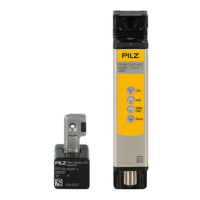
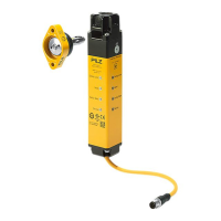
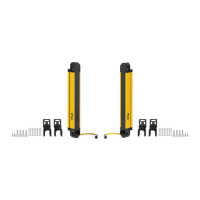
} Use two screws to mount the safety switch on the frame.
a Screw for the actuator: M5 cylinder head screw, 30 mm
a Screw for the male connector: M5 cylinder head screw, 8/10 mm
} Use two 30 mm M5 cylinder head screws to attach the actuator to the gate.
The actuator should engage smoothly into the safety switch.
Maintain a slight parallel offset from the gate’s rotation point when installing the actuator.