65
BT37 MarkII: Service Manual MA200606 1.0.0
Component replacement
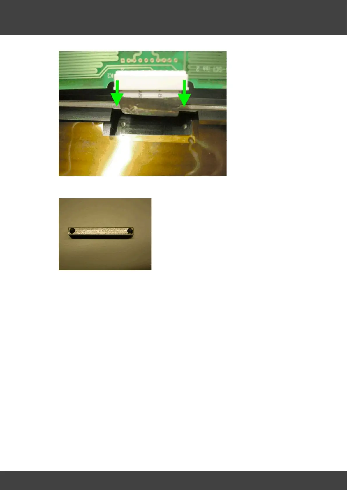
Fig.6 Move the cable locking mechanism in the direction shown to free the FCC cable
Fig.7 FCC cable support bar
8) Leave the sheet of kapton insulation that was sandwiched between the heater circuit
board and the top heater plate in position.
9) Ensure the recess in the heater plate that accepts the circuit board thermistor is
sufficiently filled with Dow Corning 340 heat sink compound so that the thermistor will
be immersed when the replacement board is fitted, see Fig.8.


 To Next Page