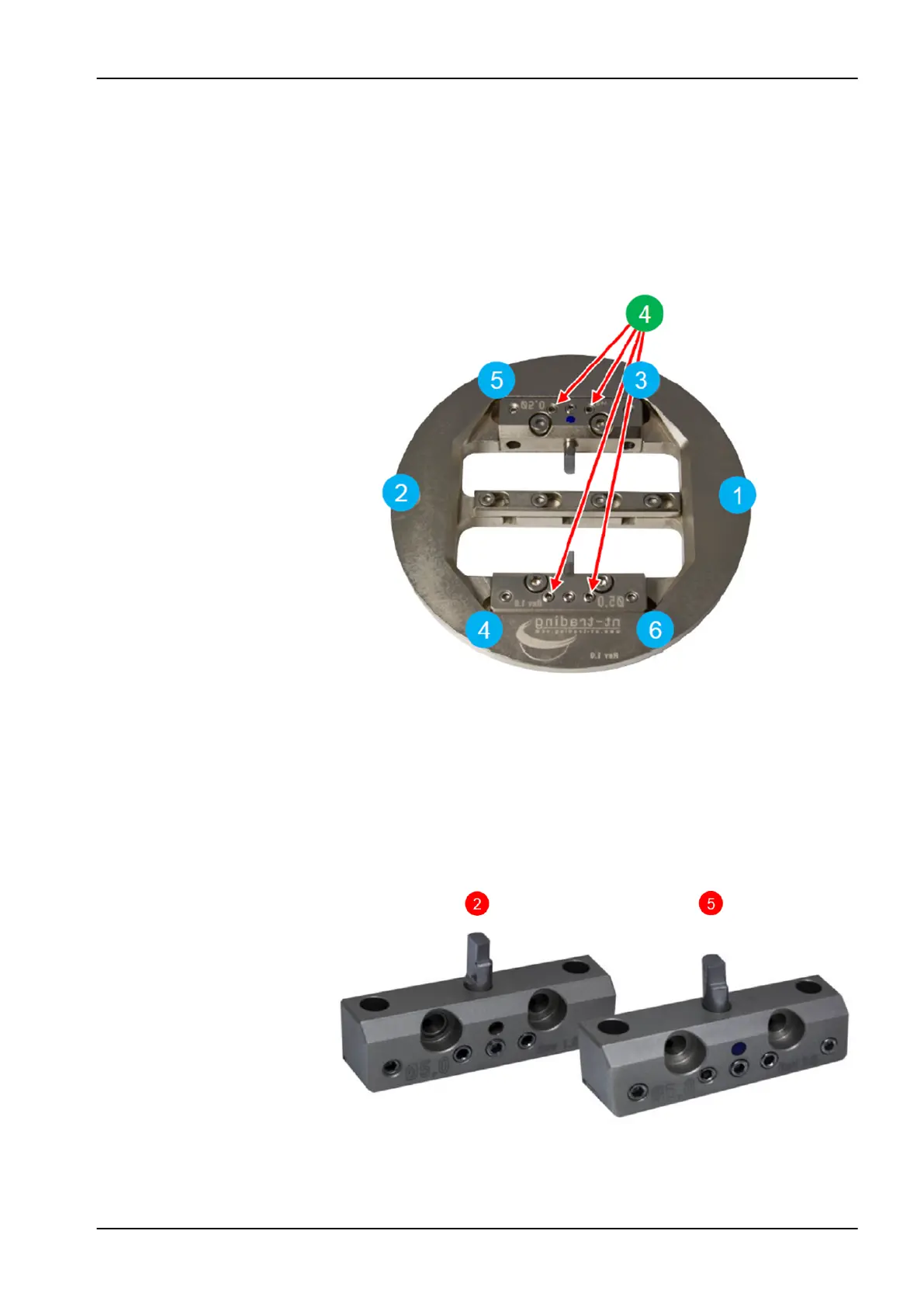
• Both bars are then inserted into the nt-trading adapter and screwed
tightly. The screws marked with (4) have to be turned back and are not
allowed to have any contact to the adapter.
• The nt-trading adapter is then fixed into the clean milling unit reception.
NOTE
Always attach the screws loosely at first and then tighten in the same
order (1) - (6).
• The test pins are milled directly on the milling unit with the scripted test
program available from your local dealer. A 2 mm metal tool (T2) is
required for the milling process.
15.3.3.3 Measurement
• The two test pins are unscrewed from the adapter
• The test pins have to be clean and free of burrs for measuring
• width (X-axis) (1)
• length (Y-axis) (2)
15 Adapters
User's manual Planmeca PlanMill 60 S 65