Chapter E - DIMAX3 DIGITAL SYSTEM ADJUSTMENT
E-12 Planmeca Proline CC panoramic x-ray
Technical Manual
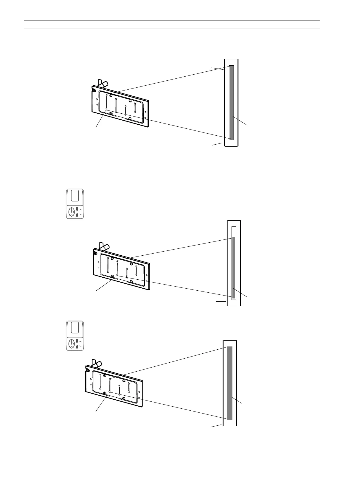
The beam image should appear within the borders of the rectangle marked on the alignment tool
(if the beam is not correctly aligned see section
“Radiation beam adjustment” on page E-14).
Figure 15
If the beam from the first slot is correctly aligned you should check the beam alignment of the
other slots. Note that the height of the other beams will vary as the slots are of different sizes.
Press the horizontal segment selection key to select the next primary slot. The number 1 will
appear on the horizontal sector display. This is the second primary slot. Repeat the previously
described alignment checking procedure for this beam. If this beam is not aligned correctly refer
to section
“Radiation beam adjustment” on page E-14 for information on how to align the beam.
When it has been checked the number 2 and number 3 slots must be checked.
Figure 16
If the x-ray unit is equipped with the Transversal slicing system, the slot number 1 is replaced
with the slot number 7. The radiation beam from slot number 7 must be slightly wider than the
NORMAL BEAM and the same height as the rectangle marked on the alignment tool.
Figure 17
UP
DOWN
PM 2002 CC X-RAY BEAM ALIGNMENT SCREEN no. 50972
NOTE: DO NOT LEAVE SCREEN IN DAYLIGHT
Primary slot number 0
Alignment rectangle
Beam
Beam alignment tool
1
UP
DOWN
PM 2002 CC X-RAY BEAM ALIGNMENT SCREEN no. 50972
NOTE: DO NOT LEAVE SCREEN IN DAYLIGHT
Primary slot number 1
Beam
Beam alignment tool
7
UP
DOWN
PM 2002 CC X-RAY BEAM ALIGNMENT SCREEN no. 50972
NOTE: DO NOT LEAVE SCREEN IN DAYLIGHT
Primary slot number 7
Beam
Beam alignment tool