Chapter E - DIMAX3 DIGITAL SYSTEM ADJUSTMENT
Planmeca Proline EC X-ray unit E-35
PATIENT POSITIONING MECHANISM
Technical Manual
Measure the distance between the line on the alignment ruler and the x-line on the ball phan-
tom (Fig. 63). The distance must be less than 1mm.
Figure 63 180° position
If the distance between the line on the alignment ruler and the x-line on the ball phantom is
more than 1mm, the sensor head position must be adjusted. Adjust the sensor head towards
the ball phantom’s x-line until the distance is less than 1mm according to the instructions
given in section
“Adjusting the position of the sensor head” on page E-35. Correct only half of
the deviation, so that the deviation will be the same in both the 180° and 0° positions.
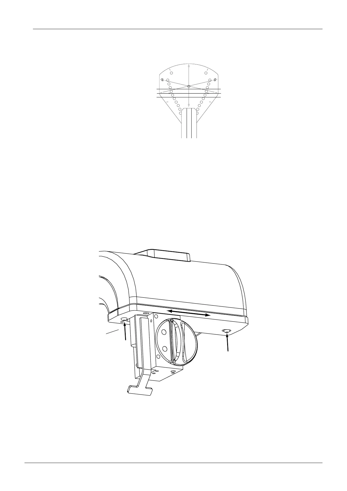
4.3 Adjusting the position of the sensor head
The position of the sensor head can be slightly adjusted. Loosen the two screws that hold the
sensor head in rotating unit and move the sensor head to required position.
Figure 64
START
END
PLANMECA No.50971
X-LINE
Y-LINE
X-LINECA.EPS
Alignment ruler
Ball phantom
Tubehead side
Sensor head side
D2_adjsenshead_1.eps
Loosen the screws.