Point Grey Flea3 GigE Technical Reference 6 Input/Output Control
6 Input/Output Control
6.1 General Purpose Input/Output (GPIO)
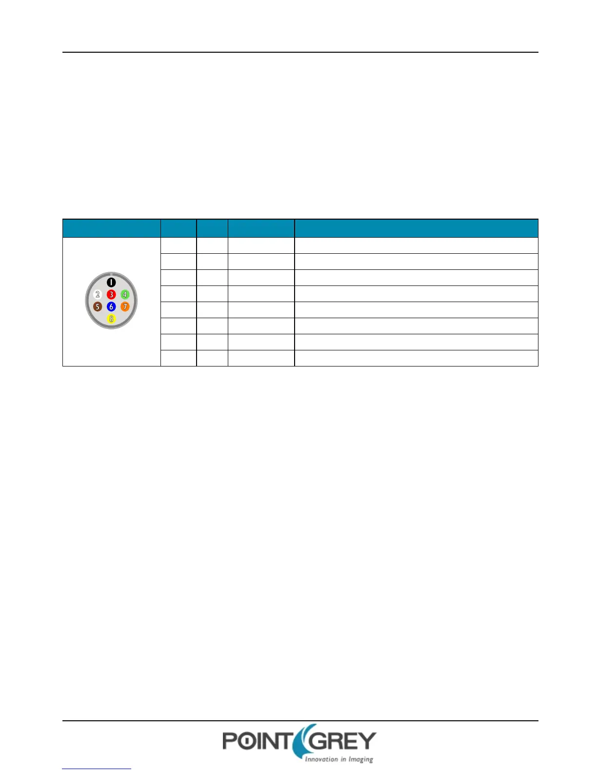
The camera has an 8-pin GPIO connector on the back of the case; refer to the diagram below for wire color-coding. The
connector is a Hirose HR25 8 pin connector with part number: HR25-7TR-8SA. The male connector is part number:
HR25-7TP-8P.
Table 6.1: GPIO pin assignments (as shown looking at rear of camera)
Diagram Color Pin Function Description
Black 1 I0 Opto-isolated input (default Trigger in)
White 2 O1 Opto-isolated output
Red 3 IO2 Input/Output/serial transmit (TX)
Green 4 IO3 Input/Output/serial receive (RX)
Brown 5 GND Ground for bi-directional IO, V
EXT
, +3.3 V pins
Blue 6 OPTO_GND Ground for opto-isolated IO pins
Orange 7 V
EXT
Allows the camera to be powered externally
Yellow 8 +3.3 V Power external circuitry up to 150 mA
Power must be provided through the GPIO interface. The required input voltage is 12 - 24 V DC.
For more information on camera power, see Powering the Camera.
For details on GPIO circuits, see GPIO Electrical Characteristics.
Revised 10/29/2013
Copyright ©2010-2013 Point Grey Research Inc.
31