Point Grey Flea3 GigE Technical Reference 6 Input/Output Control
6.8 GPIO Electrical Characteristics
Both the opto-isolated input and output have over current protection.
The output is open collector and thus requires a pull-up resistor to operate. The rise time and bias current will be
determined by the resistor value chosen. If the camera is generating an output signal that approaches the rise time plus
the fall time of the opto-isolated circuit, care must be taken to optimize the pull-up resistor chosen to minimize the rise
time while still remaining within the current limits of the output circuit.
To avoid damage, connect the OPTO_GND pin first before applying
voltage to the GPIO line.
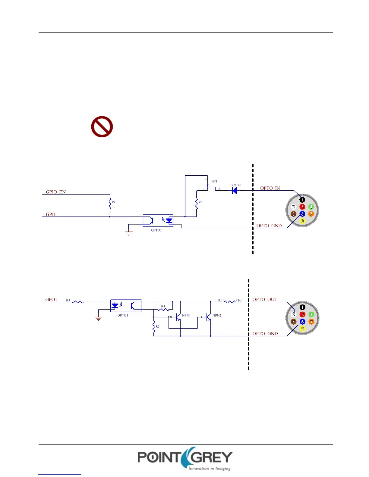
Figure 6.2: Opto-isolated input circuit
Figure 6.3: Opto-isolated output circuit
Revised 10/29/2013
Copyright ©2010-2013 Point Grey Research Inc.
37