9.8
9926806 R03 - 2015 - 2016 RANGER ETX / 570 2-SEAT 2015 - 2016 RANGER 570 CREW Service Manual
© Copyright Polaris Industries Inc.
MASTER CYLINDER
REMOVAL
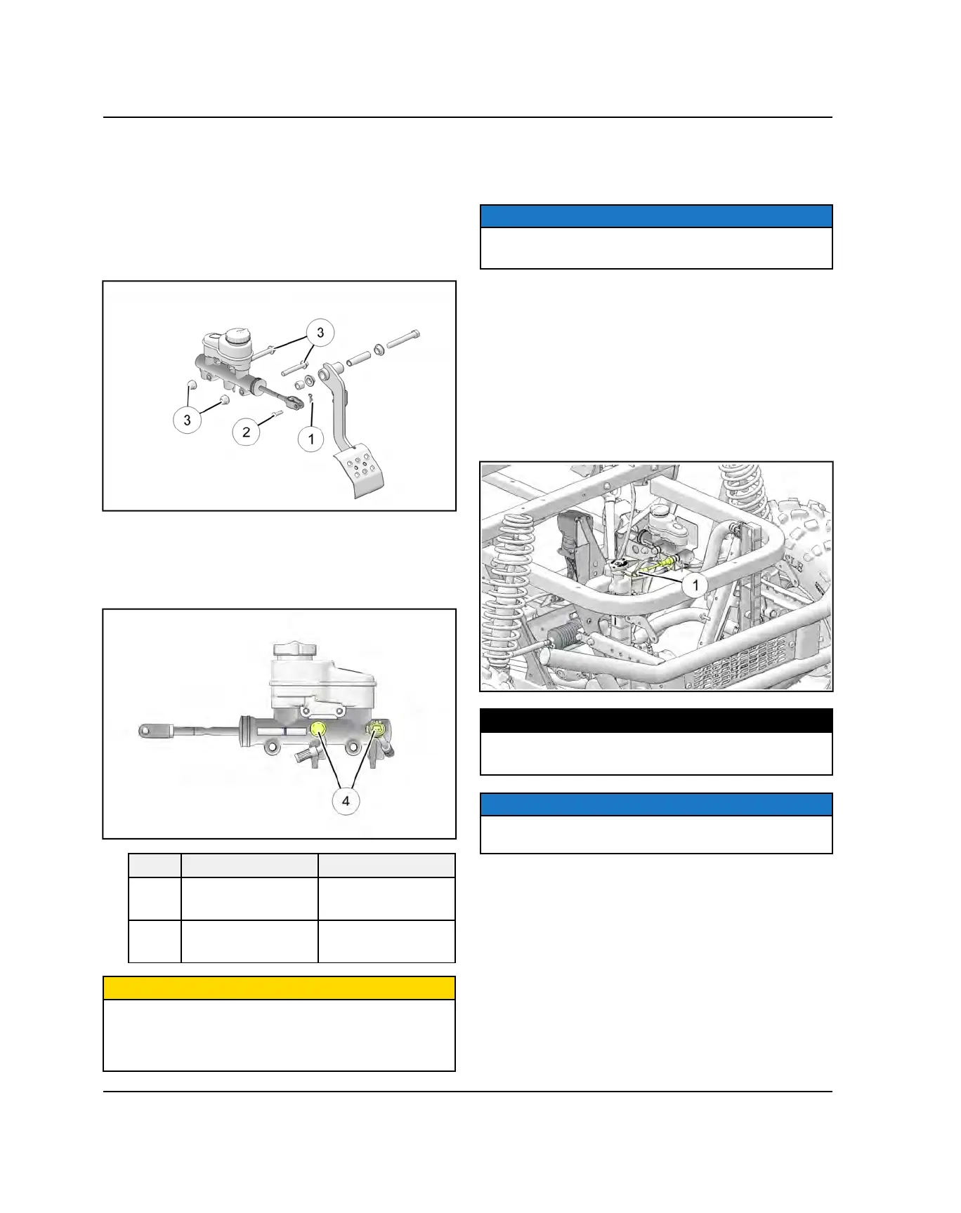
1. Remove the retaining clip
q
from the clevis pin
w
that attaches the master cylinder to the brake pedal
lever.
2. Remove LH wheel well panel to access master
cylinder.
3. Remove the two mounting bolts
e
that secure the
master cylinder to the frame.
4. Remove master cylinder and place a fluid catch
container under the master cylinder brake line banjo
bolt
r
.
REF.
DESCRIPTION NOTES
e
Mounting Bolts
Torque to 15 ft-lbs
(20 Nm)
r
Banjo Bolts
Torque to 15 ft-lbs
(20 Nm)
CAUTION
Brake fluid will damage finished surfaces.
Do not allow brake fluid to come in contact with finished
surfaces.
5. Loosen the brake line banjo bolts
r
and allow the
fluid to drain.
NOTE
Make note of front and rear brake line orientation on the
master cylinder.
6. Dispose of brake fluid properly and do not re-use.
INSTALLATION
Reverse Steps 1-5 for master cylinder installation. Refer
to the torque specifications in the illustration.
BRAKE PRESSURE SWITCH
The brake pressure switch
q
is located on the front
brake line outlet on the master cylinder.
TORQUE
Brake Pressure Switch / Banjo Bolt:
15 ft-lbs (20 Nm)
NOTE
Always replace banjo washers if fastener is loosened or
removed.
BRAKE SYSTEM

 Loading...
