Linking Multiple SoundStructure Devices with OBAM
7 - 19
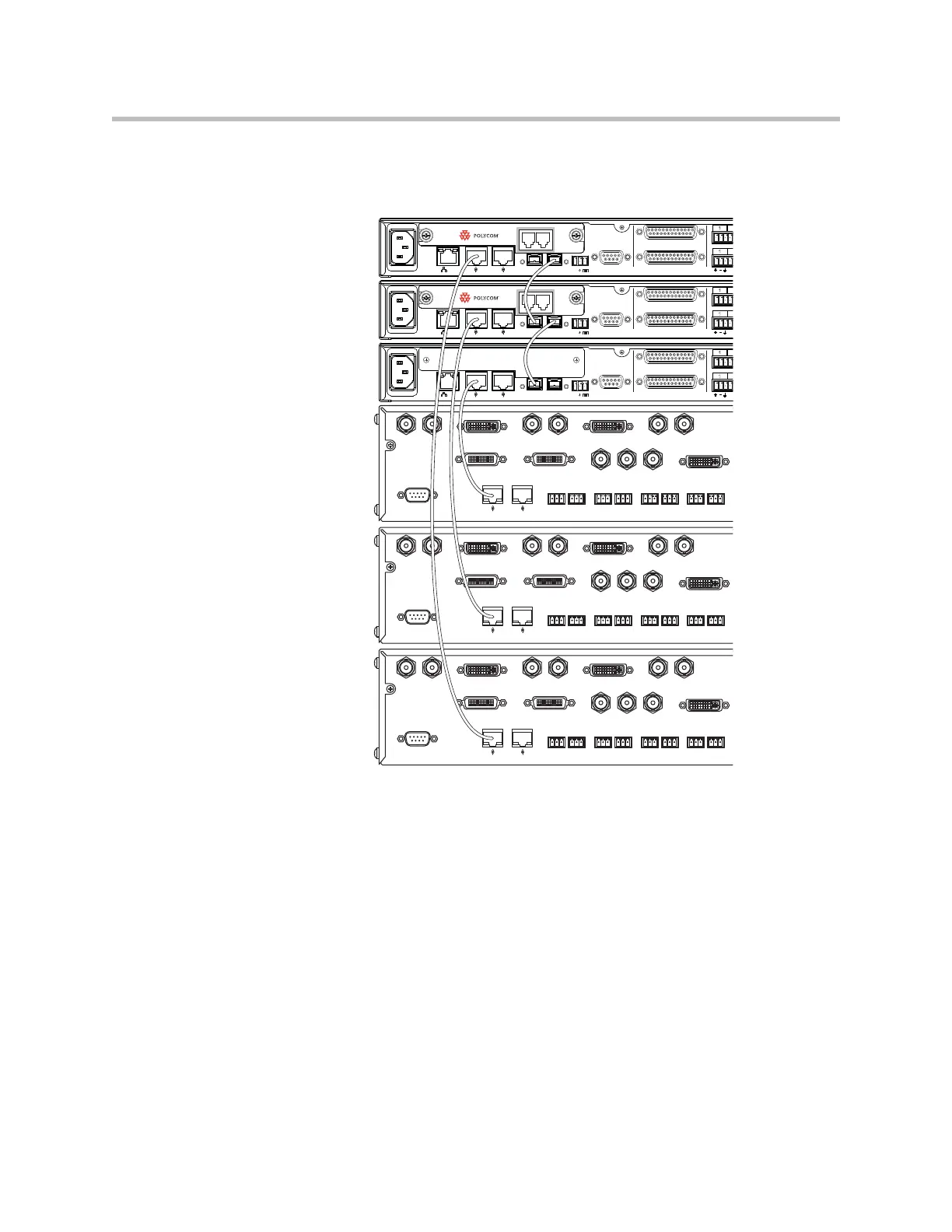
ture with Bus ID 2, and HDX 3 is connected to the SoundStructure with bus ID
3. Chapter 16 includes details for the pin outs of the Clink2 cable required to
connect between the HDX and SoundStructure devices.
As described in Chapter 6, when a Polycom HDX video codec is muted, it will
send a command to mute the virtual channel or group with the name "Mics".
When using multiple HDX video codecs over Clink2, if any HDX codec is told
to mute via a button press on a microphone, an IR key press, or a control
system command to the HDX codec, then the channels defined by "Mics" will
be muted within SoundStructure. Volume up and volume down operate in a
similar manner when any HDX video codec receives a volume up or volume
down command, the SoundStructure will receive a command to adjust the
fader of the "Amplifier" virtual channel.
If multiple HDX codecs are being used independently within a SoundStruc-
ture system, ensure that the SoundStructure system does not include virtual
channel names "Mics" or "Amplifier" or if those names are used, ensure that
they are defined in such a way that the system operates as desired. An easy
way to customize the definition of "Mics" and "Amplifier" virtual channels is
to define submixes with the name “Mics” and “Amplifier” and then use pre-
sets or partial presets to mute and unmute the desired signals to these
PIN 2: TXD
PIN 3: RXD
PIN 5: GROUND
PIN 7: CTS
PIN 8: RTS
LAN
C-LINK2
OBAM IR
RS-232
REMOTE CONTROL 2
IN OUT
1
1
12V
REMOTE CONTROL 1
PHONE LINE
PIN 2: TXD
PIN 3: RXD
PIN 5: GROUND
PIN 7: CTS
PIN 8: RTS
LAN
C-LINK2
OBAM IR
RS-232
REMOTE CONTROL 2
IN OUT
1
1
12V
REMOTE CONTROL 1
PHONE LINE
PIN 2: TXD
PIN 3: RXD
PIN 5: GROUND
PIN 7: CTS
PIN 8: RTS
LAN
C-LINK2
OBAM IR
RS-232
REMOTE CONTROL 2
IN OUT
1
1
12V
REMOTE CONTROL 1
HDX 3
Bus ID 1
Bus ID 2
Bus ID 3
HDX 2
HDX 1