Design Guide for the Polycom SoundStructure C16, C12, C8, and SR12
9 - 20
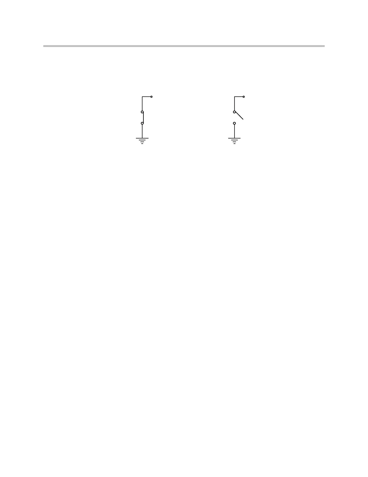
As shown in the following figure, when the logic output pin is set to 1 the
output pin allows current to flow from the logic output pin to the chassis
ground, thus completing a signal circuit path. When the logic output is set to
0, no current flows from the logic output pin to ground and the circuit is open.
Logic Arrays
It is possible to link multiple logic pins together in a logic array. A logic input
array is useful when there are more than two logic states that are important.
For example, in a split and combine room with two movable partitions, there
are four different combinations that must be considered as shown in the fol-
lowing figure with a logic input array that consists of two input pins. These
two pins allow all four combinations of the room partitions to be specified. In
the events section, we’ll see how to use the logic array values as sources and
execute different presets based on the value of the logic array.
When defining logic array pins, the pin with the highest array index is the
most significant bit. As shown in the figure, creating a two pin logic input
array creates TwoPinArray[2] and TwoPinArray[1] pins as part of the array
TwoPinArray. TwoPinArray[2] is the most significant bit in the two bit word.
Logic Output = 0
Low (Off)
Logic Output = 1
High (On)
Chassis GroundChassis Ground
Logic Output PinLogic Output Pin