© 2006 Schneider Electric All Rights Reserved
PowerLogic
®
Series 800 Power Meter 63230-500-224A1
Chapter 4—Wiring 6/2006
EN–32
ENGLISH
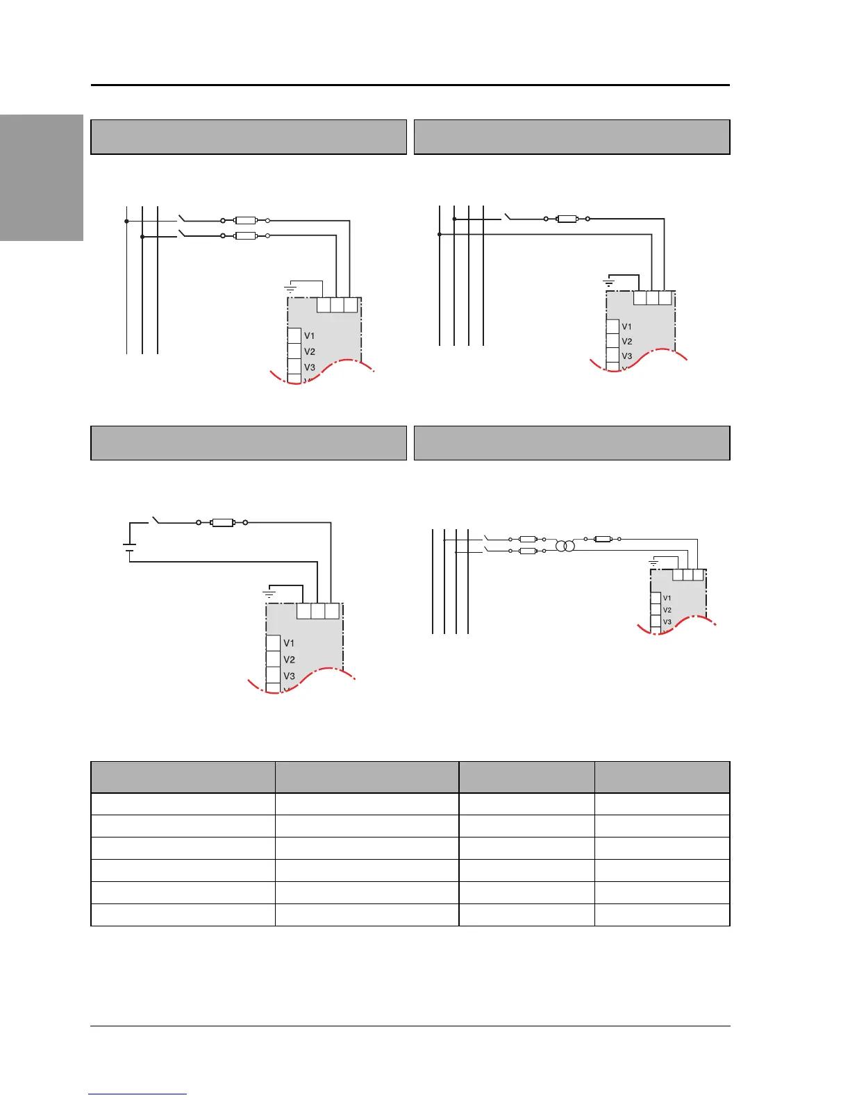
Figure 4 – 12: Direct Connect Control Power
(Phase to Phase)
Figure 4 – 13: Direct Connect Control Power
(Phase to Neutral)
Figure 4 – 14: Direct Connect Control Power (DC
Control Power)
Figure 4 – 15: Control Power Transformer
Connection
L1 L2 L3
8
9
10
11
123
PM800
Phase to Phase only when
voltage<415
±
10 % VAC max.
PLSD110072
L1 L2 L3N
8
9
10
11
123
PM800
Phase to Neutral only when
voltage<415
±
10 % VAC max.
PLSD110071
8
9
10
11
123
DC Control Power
100 Vdc < V < 300 Vdc
PLSD110065
L1 L2 L3N
CPT
8
9
10
11
123
PM800
Control Power Transformer
120 or 240 Vac Secondary 50 Va max.
PLSD110070
Table 4 – 5: Fuse Recommendation
Control Power Source Source Voltage (V
s
) Fuse Fuse Amperage
CPT V
s
≤125 V FNM or MDL 250 mA
CPT 125 < V
s
≤ 240 V FNQ or FNQ-R 250 mA
CPT 240 < V
s
≤305 V FNQ or FNQ-R 250 mA
Line Voltage V
s
≤ 240 V FNQ-R 250 mA
Line Voltage V
s
> 240 V FNQ-R 250 mA
DC V
s
≤ 300 V LP-CC 500 mA
The voltage input protection devices must be rated for the short circuit current at the connection points.